What is a Stress?
The external forces acting on a welded component cause internal deformations which are called welding stresses. Stress acting perpendicular to the sectional surface is called as normal stress, whereby a distinction must be made between tensile and compressive stress.
the Greek letter Σ (sigma) is used to denote normal welding stress. Stresses acting tangentially to the observed sectional surface are referred to as shearing stresses and represented by the Greek letter Τ (Tau).
Shear stresses (important for fillet weld design) always occur in pairs and are pointing either towards or away from the connected edges of perpendicular planes. There is no uniaxial shearing stress state.
Weld Joint design principles
Weld joint design principles are the foundation of a good weld. The design of weld joints is critical to the overall strength and stability of the structure. There are several factors that must be considered when designing weld joints.
- Fillet welds are always designed on the basis of shear stress on the throat (a).
- A weld joint of the type that will require the minimum amount of weld metal shall be selected. Use the smalled practical root opening and groove angle for butt weld design.
- For example, if a 20-degree groove can be welded satisfactorily there is no reason for having a greater groove angle. This will not only reduce distortion and residual stresses but also the need and cost of PWHT and any rework due to distortion.
- Butt weld on thick components shall be designed using Double V or U groove welds to reduce the amount of weld metal, and residual stresses and to control distortion.
- Joints shall be made with the best possible fit-up as joints with a larger gap require additional cost and resources.
Stress in Fillet Welds
Fillet Weld Joints can be loaded with stress in tension, compression or shear stress. But out of these three types, only shear stress is responsible for a Fillet Weld joint failure under loading. Fillet Weld always fails in shear loading.
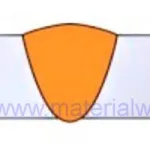
The critical dimension with regards to the strength of a fillet weld or butt weld is the throat size (a) for fillet and throat dimension (s) for a butt weld joint.
This is the minimum thickness of the weld on a straight line passing through its root. For stress calculation of a 45° fillet weld with the leg length (L), the theoretical value of the throat thickness is 1/√2 or 0.707L, where L is the leg length of the fillet weld. In actual practice, the throat thickness of fillet welds has to be kept within the limit of 0.6L and 0.9L.
Stress in fillet welds shall be considered as shear applied to the effective area for any direction of the applied load. The flow of stress takes place via the weld throat in a fillet weld and the weld throat bears the maximum stress.
When stress is applied in a fillet weld joint, the throat will be the failure location if the load is exceeded the maximum load capacity. This is the reason that the design calculations for fillet welds consider throat size calculation.
For a layman’s calculation of Stress level in Fillet Below, you can use the below equation/ formula to help you to find the stress value, throat size (a), or effective weld length (L) if you know any of these 2 components:
Stress (N/mm2) = (Load, P)/ (weld Length x Weld Throat, a)
You can use this formula to calculate the stress level, throat size (a), or effective weld length (L) for fillet welds under Shear Stress, see below sketch.
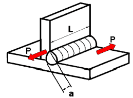
In engineering practices, Fillet Weld Calculations are carried out considering their application for shear loading (as fillet welds are subjected to shear stress mainly).
The most important factor is to find out the allowable shear stress or Design Shear Stress. As a thumb rule, you can consider the design shear stress equal to half of the base material’s Yield Strength.
The reason for considering the value to half of the Yield strength in a Fillet Weld design is because of the inherent joint design. Fillet welds have always lack of root penetration (They are not full penetration welds) and higher combined thickness compare to butt welds.
As explained above, ISO Standards use throat size (a) for fillet weld calculation, however, in our American Codes, Leg length (z) size is considered for design calculation.
This stands practically fit in the case of a Mitre Fillet Weld, where we can prove a relationship between the Throat Size (a) and Leg length Size (z) as given below:
Throat size (a) = 0.7 x Leg Length Size (z) or Leg Length (z) = 1.4 x throat size (a)
Although, this equation will not work in the case of a concave fillet weld or Convex Fillet weld as throat size will not practically represent the Leg Length or vice-versa.
How to calculate shear stress in a Fillet Weld
Fillet welds are designed for shear stress loading. In cases where the applied load is not perpendicular to the fillet weld, then the weld will be in shear stress.
This will reduce the load-carrying capacity of the weld significantly. Due to this issue, at the stage of weld joint design, it is preassumed that shear load (stress) will be applied to the welds as illustrated in the below sketch.

Here, the weld is parallel to the applied load. The tension forces are pulling the plates being joined in opposite directions, and the resultant weld area is under shear stress loading similar to a lap joint.
In a welded shear loading component the tensile properties of the welding wire or electrode can’t be considered. because the tensile strength is reduced by a factor (usually reduced by 70%) in order to assure safety.
As specified in AWS D1.1 the minimum tensile strength of the weld metal is multiplied by a factor of 0.30 to get the allowable shear stress on the weld as given in the below equation:
allowable stress, Fv = 0.30 FEXX (1.0 + 0.50 sin1.5 θ)
where
Fv = allowable unit stress
FExx = electrode classification number, i.e., electrode strength classification
θ = angle between the direction of force and the axis of the welding element, degrees
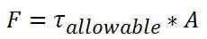
Considering the above safety factor in our stress calculation where stresses are shear stress,τ not the tensile stress, we can see:
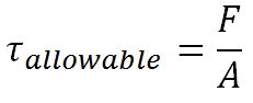
Where,
τ: Maximum allowed shear stress in the weld,
F: load-bearing capacity of the weld
A: welding effective area.
Assume a weld of 10-inch length at two places on both sides is made with an E7018 welding electrodes that have a minimum tensile strength of 70,000 psi as shown below.

So, the allowable shear stress for the welds will be= 70,000 psi x 0.30 = 21,000 psi. (a 70% reduction)
If the size of the welds is 1/2-inch as shown in the above figure leg length fillets then the shear strength (load carrying capacity) of the welds will be:
as calculated earlier, the allowable shear stress is 70,000 x 0.30 = 21,000 psi.
To get A (effective area of the weld), first, we need to convert the leg length to the throat size. as we know a= z x 0.707 so we need to multiply the leg length as (1/2 x 0.707 = 0.3535 inches) times the length (10 inches) times 2 welds.
The effective area of total weld will be : 10 in x 0.3535 in x 2 = 7.07 sq-in.
We can now solve for F.
F = 21,000 x 7.07 = 148,470 lbf
Here as the welding is carried out parallel to the load, the stress is seventy percent less compared to the welding carried out in the perpendicular direction to the load applied.
Calculation of Alternative Allowable Fillet Weld Stress
In the case of a one linear fillet joint or weld with multiple fillet welds consisting of parallel linear fillet welds, all loaded at the same angle and loaded in-plane through the centroid of the weld group, the
allowable stress may be determined by Formula :
Fv = 0.30 FEXX (1.0 + 0.50 sin1.5 θ)
where
Fv = allowable unit stress
FExx = electrode classification number, i.e., electrode strength classification
θ = angle between the direction of force and the axis of the welding element, degrees
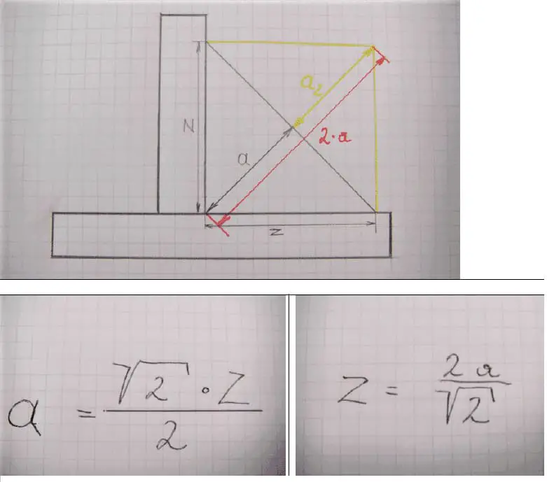
Relationship between Leg Length z and Throat Size a
The ‘a’ size is calculated from the previous corner of the workpiece before welding until the 45° created middle of the welding seam.
The sidewall – connection between the welding seam and the base material is called – ‘z’. The ‘a’ size is nothing more than the Hypotenuse of an isosceles triangle.
For a fillet weld with equal leg lengths, the cross-section triangle is a right-angle triangle with angles of 45 degrees in each corner. The relationship between weld throat, a, and leg length z is given by:
a ≈ 0.7z and z ≈ 1.4 a
(For the maths-minded, 0.7 is 1/√2 and 1.4 is √2).
The below sketch gives the calculation for various stresses in the welds.


Dr. Sandeep Kumar
Hi, I'm Dr. Sandeep Kumar. I am a passionate Welding & Material Expert with a Ph.D. and M.Sc. in Welding Engineering. As an International Welding Engineer (IWE), I bridge the gap between academic research and practical industrial application. My goal is to share high-level knowledge on metallurgy, welding technical knowledge, and engineering best practices to help professionals and students succeed in the field.