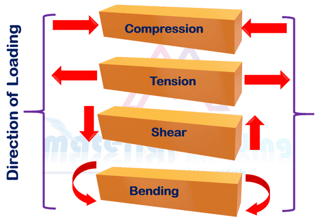
Welding joints are subjected to various types of loading and stresses such as longitudinal, transverse, shear, fatigue and torsional loads as shown in figure 1 and being used for various application e.g. railway, aerospace, oil & gas, structural & heavy fabrication to name a few.
The basic for the welding design based on the understanding of these stresses, how they work and affect the component.
Figure 1. Various types of stresses in welding structures Various types of stresses in welding structures
Types of Stresses in Welding Joints
The first important consideration for a design is Stress being subjected to the part.
There are several types of stresses that can occur in welding joints:
Torsion stresses: These occur in the joint when there is a twisting force acting on the welded structure.
Shear stresses: These occur in the joint when there is a force acting parallel to the surface of the welded structure.
Bending stresses: These occur in the joint when there is a force acting perpendicular to the surface of the welded structure.
Residual stresses: These are stresses that remain in the material after welding has been completed. They can be caused by the cooling of the metal and can result in warping or distortion of the joint.
Thermal stresses: These are stresses that are caused by the heating and cooling of the metal during the welding process. They can result in cracking or distortion of the joint if not properly managed.
Mechanical stresses: These are stresses that are caused by the forces applied to the joint during welding, such as from contraction or expansion of the metal. They can also be caused by external forces such as vibration or impact.
Fatigue stresses: These are stresses that occur over time due to repeated loading and unloading of the joint. They can lead to cracking or failure of the joint if not properly managed.
Creep Stresses: These are long term stresses that occur in the welded joints under a constant load over a long period of time. They can lead to deformation and failure of the joint if not properly managed.
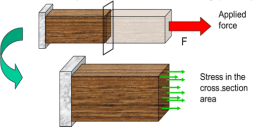
Stress in welding joint is defined as load (or force) divided by the cross-sectional area (CSA) of the component subjected to load. If the force, F, is in newtons (N) and the CSA area in millimeters squared (mm2), then the tensile stress, given the symbol σ, is in newtons per millimeter squared (N/mm2), which is the same as megapascals (MPa).
Stresses can act either as a tensile stress (pulling apart) or a compressive stress (squashing together) but is calculated the same way for each, i.e. load over CSA. Tensile stress is often considered dangerous because it requires a tensile stress to spread a crack.
Strain in welding joint
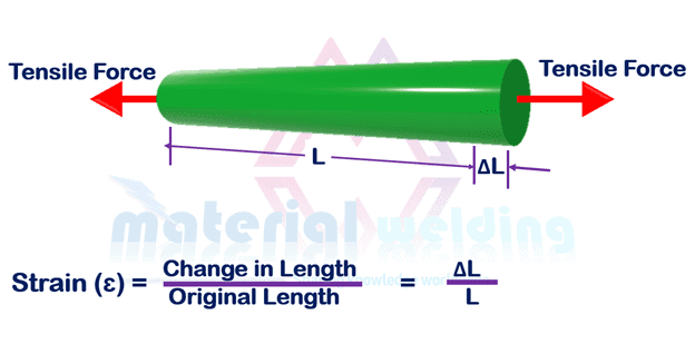
Strain is the change is length caused by the application of a force divided by the original length. Refer figure 3, assuming the original length L, then the change in length is shown as ΔL. The symbol for the strain is the Greek letter epsilon, ɛ.
Figure 3. tensile strength application
Shear Stress in welding joint
Shear Stress in welding joint are the forces that produces an opposite but parallel sliding motion between two parts in the same plane as shown in figure 1. In materials, plastic deformation occurs on planes of high shear stresses. In welding, fillet weld are mostly designed for the shear stress.
Welding design is the process of planning and creating the layout, dimensions, and specifications for a welded structure or component.
It involves taking into consideration factors such as the type of material being welded, the type of welding process to be used, the size and shape of the structure, and the loads and stresses that the structure will be subjected to.
Welding design also includes selecting the appropriate welding techniques, procedures, and equipment to ensure that the finished structure is strong, safe, and meets all necessary codes and standards.
It involves the selection of welding symbols, joint design, preparation and fit-up, welding sequence and procedure, and inspection methods.
It’s an important step in the welding process as it helps to ensure that the final product will be safe, durable, and suitable for its intended purpose.
Welding design calculation
Welding design calculations are used to determine the size, shape, and number of welds required for a structure or component, as well as the amount of filler metal needed. These calculations help to ensure that the finished structure will be strong and safe, and that it will meet all necessary codes and standards. Some of the key calculations involved in welding design include:
Strength calculations: These calculations are used to determine the size and number of welds required to provide adequate strength for the structure or component. For example, to determine the size of a fillet weld required to join two plates together, the allowable stress in the weld metal, the effective throat size and the leg size are calculated.
Load calculations: These calculations are used to determine the loads and stresses that the structure or component will be subjected to, and to ensure that the welded structure will be able to withstand these loads and stresses. For example, to determine the maximum load that a bridge will be subjected to, the weight of the bridge, the weight of the vehicles that will be crossing the bridge, and the wind load acting on the bridge are calculated.
Joint efficiency calculations: These calculations are used to determine the strength of a joint as a percentage of the strength of the base metal. For example, a lap joint with a fillet weld is designed with a joint efficiency of 75%. This means that the strength of the joint is 75% of the strength of the base metal.
Distortion calculations: These calculations are used to determine the amount of distortion that will occur as a result of welding, and to take steps to minimize or control that distortion. For example, when welding a pipe, the thermal expansion and contraction of the pipe must be calculated to prevent warping and bending of the pipe.
Fatigue calculations: These calculations are used to determine the fatigue life of a welded structure and to ensure that the structure will be able to withstand cyclic loading over time. For example, the fatigue life of a welded joint on a crane boom is calculated to ensure that the joint will withstand the cyclic loading caused by the crane’s movement over time.
Creep calculations: They are used to determine the creep life of a welded structure and to ensure that the structure will be able to withstand constant loads over time. For example, the creep life of a welded joint in a high-pressure pipeline is calculated to ensure that the joint will withstand the constant loads caused by the high-pressure fluid over time.
It’s important to note that these calculations should be done by experienced engineers or welding experts and using specialized software, to ensure the accuracy and integrity of the design.
What is one characteristic of a good welding design?
One important characteristic of a good welding design is that it should ensure the structural integrity and safety of the final product. This means that the welded structure or component should be able to withstand the loads and stresses that it will be subjected to without failing or becoming damaged. A good welding design should also consider the service life of the structure and the potential for fatigue, corrosion and creep.
Material Welding is run by highly experienced welding engineers, welding trainers & ASNT NDT Level III bloggers.
We strive to provide most accurate and practical knowledge in welding, metallurgy, NDT and Engineering domains.