ASME Section IX of the Boiler and Pressure Vessel Code provides guidelines for the qualification of welders, welding operators, brazers, and brazing operators. The acceptance criteria for welder qualification tests are outlined in this code section.
In ASME Section IX, the acceptance criteria for welder qualification tests are based on several factors, including the welding process, base material, filler material, welding position, and joint configuration. Here are some key points to consider:
Welding Procedure Specification (WPS): Before a welder can be qualified, a suitable WPS must be prepared and approved. The WPS provides detailed instructions for welding a specific joint and includes information about the welding process, base and filler materials, preheat and post-weld heat treatment requirements, welding positions, and other essential variables.
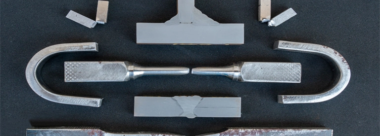
Test Coupon: A test coupon, or test piece, is a sample joint that the welder will use to demonstrate their welding skills. The dimensions and specifications of the test coupon should conform to the requirements specified in the applicable WPS.
Visual Examination: After welding the test coupon, a visual examination is conducted to assess the weld’s appearance and identify any visible defects. The criteria for acceptable and unacceptable visual weld quality are outlined in ASME Section IX.
Non-Destructive Examination (NDE): Depending on the requirements of the specific application and the applicable code, additional non-destructive examination methods such as radiographic testing (RT), ultrasonic testing (UT), magnetic particle testing (MT), or liquid penetrant testing (PT) may be required to evaluate the weld’s quality.
Mechanical Testing: Mechanical testing involves subjecting the test coupon to various tests to assess its mechanical properties. Common mechanical tests include tensile testing, bend testing, impact testing, and macro etch testing. The acceptance criteria for these tests are provided in ASME Section IX and depend on factors such as the base material, welding process, and joint configuration.
ASME Section IX Visual Testing Acceptance Criteria
In ASME Section IX, the acceptance criteria for visual testing (VT) are provided to evaluate the appearance and visual quality of welds. These criteria help determine whether a weld meets the required standards and is acceptable for its intended application.
Prior to cutting bend specimens, all surfaces of plate coupons, excluding designated “discard” areas, must undergo a visual examination per QW-194. Similarly, for pipe coupons, a visual examination per QW-194 (as outlines below) must be conducted over the entire circumference, both inside and outside.
Visual examination of the welds must be conducted without the need for magnification.
The welds should exhibit complete fusion, indicating a thorough joining of the materials.
There should be no visible cracks or indications of porosity in the welds.
Additionally, there should be no signs of burning through the tube wall, indicating excessive heat or penetration.
ASME Section IX Radiographic Testing-RT Acceptance Criteria
Welders or welding operators can be qualified through volumetric non-destructive examination (NDE) as allowed in QW-304 for welders and QW-305 for welding operators.
When qualifying through volumetric NDE, the minimum length of the coupon(s) to be examined should be 6 inches (150 mm).
For pipe welds, the examination should cover the entire circumference of the weld.
However, for small diameter pipe, multiple coupons of the same diameter may be required, but the maximum number should not exceed four consecutively made test coupons.
The examination technique and acceptance criteria should follow the guidelines outlined in QW-191.
Acceptance Criteria
Linear Indications characteristics:
Cracks, incomplete fusion, inadequate penetration, and slag are represented as linear indications on the radiograph.
The length of these indications is more than three times their width.
Rounded Indications characteristics:
Porosity and inclusions (e.g., slag or tungsten) appear as rounded indications on the radiograph.
The length of these indications is three times their width or less.
They can be circular, elliptical, or irregular in shape and may have tails. Their density can vary.
Acceptance Criteria for Linear Indications:
Any type of crack or zone of incomplete fusion or penetration is considered unacceptable.
Elongated slag inclusions exceeding specified lengths based on material thickness are unacceptable.
Groups of slag inclusions in line are evaluated based on aggregate length and distance between imperfections.
Acceptance Criteria for Rounded Indications:
The maximum permissible dimension for rounded indications is determined based on a percentage of material thickness or a specified minimum value.
The number of acceptable rounded indications is limited based on weld length and material thickness.
Charts in Figure QW-191.1.2.2(b)(4) define the maximum acceptable types of rounded indications based on their configurations.
Rounded indications with a diameter less than a specified value are not considered in radiographic acceptance tests for welders and welding operators within certain material thickness ranges.
ASME Section IX Ultrasonic Testing-UT Acceptance Criteria
In ASME Section IX, the acceptance criteria for ultrasonic testing (UT) are provided to assess the integrity and soundness of welds and base materials. The key points regarding UT acceptance criteria in ASME Section IX:
Indication Sizing: The acceptance criteria specify the maximum allowable size of indications, such as cracks, lack of fusion, lack of penetration, porosity, and inclusions. The size is typically measured in terms of length, height, width, or equivalent flaw size.
Location and Orientation: The acceptance criteria define the acceptable location and orientation of indications within the weld or base material. Certain regions, such as the heat-affected zone (HAZ), may have specific requirements for allowable indications.
Rejection Limits: The acceptance criteria establish the rejection limits for indications based on their type, size, location, and other relevant factors. Indications exceeding these limits are considered unacceptable and can lead to rejection of the weld or component.
Evaluation Techniques: The acceptance criteria outline the evaluation techniques to be used during UT, such as amplitude-based sizing, echo dynamics, time-of-flight diffraction (TOFD), or phased array ultrasonics (PAUT). The specific technique depends on the application and the capabilities of the testing equipment.
Reference Standards: The acceptance criteria may reference specific codes, standards, or procedures to establish the acceptance criteria for UT. These standards provide guidelines for interpreting and evaluating the ultrasonic test results.
Ultrasonic examination in QW-142 for welders and QW-143 for welding operators is applicable to test welds with a minimum thickness of 1/4 inch (6 mm).
Ultrasonic examinations must adhere to a written procedure that complies with Section V, Article 1, T-150, and the requirements of Section V, Article 4 for methods and procedures.
Acceptance criteria for qualification test welds, as outlined in QW-191.2.2, involve the sizing and evaluation of indications.
Indications characterized as cracks, lack of fusion, or incomplete penetration are considered unacceptable, regardless of their length.
Relevant indications are those exceeding 1/8 inch (3 mm) in length and are deemed unacceptable based on specific length limits depending on the material thickness (t):
Up to 3/8 inch (10 mm): Limit is 1/8 inch (3 mm).
From 3/8 inch to 2 1/4 inches (10 mm to 57 mm): Limit is 1/3 t.
Over 2 1/4 inches (57 mm): Limit is 3/4 inch (19 mm), where t represents the weld thickness excluding any allowable reinforcement.
In a butt weld joining two members with different thicknesses, t is determined by the thinner thickness. If a full penetration weld includes a fillet weld, the throat thickness of the fillet is included in t.
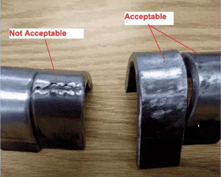
ASME Section IX Bend Test Acceptance Criteria
In ASME Section IX, the bend test is a commonly used method to evaluate the ductility and soundness of weldments. The acceptance criteria for bend testing are provided to ensure that the tested weld specimens meet the specified quality standards.
The weld and heat-affected zone of a transverse weld-bend specimen must be fully contained within the bent portion of the specimen during testing.
In guided-bend specimens, there should be no open discontinuities in the weld or heat-affected zone that exceed 1/8 inch (3 mm) in any direction on the convex surface of the specimen after bending.
Open discontinuities observed on the corners of the specimen during testing are not considered unless there is clear evidence that they are caused by lack of fusion, slag inclusions, or other internal discontinuities.
For corrosion-resistant weld overlay cladding, open discontinuities in the cladding exceeding 1/16 inch (1.5 mm) in any direction are not permitted, and along the approximate weld interface, no open discontinuity exceeding 1/8 inch (3 mm) is allowed.
Here are the key points regarding the bend test acceptance criteria in ASME Section IX:
Complete Containment: The weld and heat-affected zone of a transverse weld-bend specimen must be fully contained within the bent portion of the specimen after testing. This means that there should be no cracking or separation extending beyond the bent region.
Discontinuity Size: In guided-bend specimens, there should be no open discontinuities, such as cracks or lack of fusion, in the weld or heat-affected zone that exceed a certain size. The maximum allowable size is typically specified as 1/8 inch (3 mm) when measured in any direction on the convex surface of the specimen after bending.
Corner Discontinuities: Open discontinuities observed on the corners of the specimen during testing are generally not considered unless there is clear evidence indicating that they result from lack of fusion, slag inclusions, or other internal discontinuities.
Cladding Acceptance Criteria: For corrosion-resistant weld overlay cladding, specific acceptance criteria apply. The cladding should not have any open discontinuities exceeding 1/16 inch (1.5 mm) in any direction. Along the approximate weld interface, no open discontinuity exceeding 1/8 inch (3 mm) is permitted.
Material Welding is run by highly experienced welding engineers, welding trainers & ASNT NDT Level III bloggers.
We strive to provide most accurate and practical knowledge in welding, metallurgy, NDT and Engineering domains.


 qualification for weld overlay Application")


