Weld Defect Acceptance/Rejection Criteria for Non-Destructive Testing (NDT) Methods
Acceptance Criteria for Visual Inspection as per ASME Section VIII Div 1
(Refer: UIG-97, Page – 345 of ASME BPVC Section VIII Div 1, 2017 Edition.)
(a) The surface shall be free of any visible laminations, spalling, or cracks. Cracks in tubes shall not be repaired and shall be considered cause for rejection.
(b) For tubes, the depth of scratch shall not exceed 1/32 in. (0.8 mm). For all other material, the scratch depth shall not exceed 1/8 in. (3 mm).
For an acceptable limit of thickness reduction, Refer to UW-35 (sub-para b, page – 144) which states that:
The reduction in thickness shall not exceed 1mm (1/32 in.) or 10% of material nominal thickness whichever is less, provided that the material of the adjoining surfaces below the design thickness at any point.
Acceptance Criteria for Radiography Test (RT)
“(Refer: UW-51: Sub Para b (Page 148 and 149) and Mandatory Appendix 4 (Page 400 and Page 403) of ASME BPVC Section VIII Div 1, 2017 Edition.)“
Terminologies:
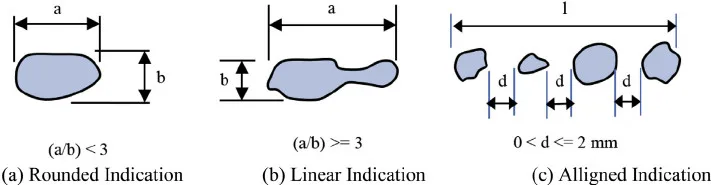
Linear Indication: Any indication with a length greater than three times the width, including cracks, lack of penetration, lack of fusion, and elongated slag inclusions.
Rounded Indication: Any indication with a length equal to or less than three times the width, which may have circular, elliptical, conical, or irregular shapes. Rounded indications can result from imperfections like porosity, slag, or tungsten, and the size of the indication should include any tails present.
Acceptance Criteria for Linear Indication (UW-51):
Cracks, lack of penetration, and lack of fusion are not acceptable in the radiography test.
Elongated indications exceeding specific lengths are considered unacceptable based on the following criteria:
For T up to 19 mm (3/4 in.), the length should be greater than 6 mm (1/4 in.).
For T greater than or equal to 19 mm (3/4 in.) and less than or equal to 57 mm (2-1/4 in.), the length should be greater than T/3, where 19 mm ≤ T ≤ 57 mm.
For T greater than 57 mm (2-1/4 in.), the length should be greater than 19 mm (3/4 in.). (Note: ‘T’ refers to the thickness of the weld metal excluding any allowable reinforcement.)
Inline groups of indications with an aggregate length exceeding T (within a length of 12T) are considered unacceptable unless the distance between successive discontinuities exceeds 6L, where ‘L’ is the length of the longest imperfection in the group.
Linear Indication in Welding
Acceptance Criteria for Rounded Indication (Mandatory Appendix 4):
Mandatory Appendix 4 provides acceptance criteria for rounded indications. Indications exceeding the following dimensions should be considered relevant:
T/10 for T less than 3 mm (1/8 in.)
0.5 mm (1/64 in.) for T from 3 mm to 6 mm (1/8 in. to 1/4 in.), inclusive
1.0 mm (1/32 in.) for T greater than 6 mm to 50 mm (1/4 in. to 2 in.), inclusive
1.5 mm (1/16 in.) for T greater than 50 mm (2 in.)
Additionally, Mandatory Appendix 4 includes tables, charts, and figures that serve as references for acceptance/rejection criteria in radiography testing.
(Refer: Mandatory Appendix 12 (Page 435) of ASME BPVC Section VIII Div 1, 2017 Edition.)
The acceptance criteria for the Ultrasonic Test (UT) are outlined below:
(a) Indications characterized as cracks, lack of fusion, or incomplete penetration are considered unacceptable, regardless of their length.
(b) Other imperfections are deemed unacceptable if the indications exceed the reference level amplitude and have lengths that exceed the following criteria:
For T up to 19 mm (3/4 in.), the length should be greater than 6 mm (1/4 in.).
For T ranging from 19 mm to 57 mm (3/4 in. to 2-1/4 in.), the length should be greater than T/3.
For T over 57 mm (2-1/4 in.), the length should be greater than 19 mm (3/4 in.).
Here, ‘T’ represents the thickness of the weld metal excluding any allowable reinforcement. In the case of a butt weld joining two members with different thicknesses at the weld, ‘T’ is considered as the thinner of the two thicknesses. If a full penetration weld includes a fillet weld, the thickness of the fillet throat should be included in ‘T’.
These criteria help determine the acceptability of indications identified during the Ultrasonic Test (UT) based on their amplitude and length, considering the thickness of the weld and the presence of specific imperfections.
Acceptance Criteria for Liquid Penetrant Test (PT) and Magnetic Particle Test (MT)
(Refer: Mandatory Appendix 8 (Page 417) for PT and Mandatory Appendix 6 (Page 412) for MT of ASME BPVC Section VIII Div 1, 2017 Edition.)
The acceptance criteria for Liquid Penetrant Test (PT) and Magnetic Particle Test (MT) are similar and are outlined below:
Terminologies:
Relevant Indications: Indications with major dimensions greater than 1.5 mm (1/16 in.) are considered relevant.
Linear Indication: Any indication with a length greater than three times the width.
Rounded Indication: Any indication with a length equal to or less than three times the width, which can be of circular or elliptical shape.
Acceptance Criteria for Liquid Penetrant Examination (Mandatory Appendix 8) and Magnetic Particle Examination (Mandatory Appendix 6):
All surfaces to be examined should be free of the following:
(a) Relevant linear indications should be rejected.
(b) Relevant rounded indications greater than 5 mm (3/16 in.) should be rejected.
(c) Four or more relevant rounded indications in a line separated by 1.5 mm (1/16 in.) or less (edge to edge) should be rejected.
These criteria determine the acceptability or rejection of indications identified during the Liquid Penetrant Test (PT) and Magnetic Particle Test (MT) based on their dimensions and alignment. Relevant indications exceeding specific dimensions or forming specific patterns are considered unacceptable and should be rejected.
Acceptance criteria for visual examination as per B31.1
Visual examination, as defined in paragraph 100.2, should be conducted according to the requirements outlined in ASME BPVC Section V, Article 9.
This examination is typically performed during the fabrication and erection of piping components to ensure compliance with design and welding procedure specifications (WPS).
It is also necessary to visually inspect completed welds in pipes and piping components to ensure they meet acceptance standards specified in (a) or comply with the limitations on imperfections stated in the relevant material specification.
Acceptance Standards for Visual Examination:
Cracks on the external surface are considered unacceptable.
Undercut on the surface that exceeds a depth of 1/32 in. (1.0 mm) or encroaches on the minimum required section thickness is unacceptable.
Undercut on the surface of longitudinal butt welds is unacceptable.
Weld reinforcement that exceeds the limits specified in Table 127.4.2-1 is considered unacceptable.
Lack of fusion on the surface is unacceptable.
Incomplete penetration is unacceptable, but this criterion applies only when the inside surface is easily accessible.
Any linear indications greater than 3/16 in. (5.0 mm) in length are considered unacceptable.
Surface porosity with rounded indications having dimensions greater than 3/16 in. (5.0 mm) or four or more rounded indications separated by 1/16 in. (2.0 mm) or less, edge to edge in any direction, are considered unacceptable. Rounded indications refer to circular or elliptical indications with a length that is less than three times their width.
Material Welding is run by highly experienced welding engineers, welding trainers & ASNT NDT Level III bloggers.
We strive to provide most accurate and practical knowledge in welding, metallurgy, NDT and Engineering domains.


 qualification for weld overlay Application")
