Welding Joint Efficiency is a term used in ASME codes for the design of welded joints in pressure vessels. Joint Efficiency refers to the strength of a welded joint with respect to the strength of the base metal.
Joint efficiency is a measure of how well a joint transfers load between two parts of a structure. It is expressed as a percentage and represents the fraction of the strength of the base material that is being utilized in the joint.
For example, a joint efficiency of 100% means that the joint is able to transfer the full strength of the base material, while a joint efficiency of 50% means that the joint is only able to transfer half of the strength of the base material.
Welding Joint efficiency is important to consider when designing and analyzing structures because it affects the overall strength and safety of the structure.
A high joint efficiency means that the structure is able to transfer load effectively, while a low joint efficiency means that the structure is not able to transfer load effectively and may be at risk of failure.
Weld Joint Efficiency Formula
Weld Joint efficiency is typically calculated as a ratio of the strength of the joint to the strength of the base material, and is expressed as a percentage. The formula for joint efficiency is:
WeldJoint Efficiency = (Joint Strength / Base Material Strength) x 100%
where:
Joint Strength is the maximum load that the joint can withstand before failure.
Base Material Strength is the maximum load that the base material can withstand before failure.
It’s important to note that the joint strength and base material strength are usually determined through testing or by using a standard formula. The results of these tests or calculations are used to determine the joint efficiency.
Also, Joint efficiency can be affected by a number of factors, including the type of joint, the quality of the fit-up, the type of welding or fastening used, and the condition of the base material.
For example, if a butt joint is able to withstand a maximum load of 10,000 pounds and the base material has a strength of 20,000 pounds, the joint efficiency would be:
This means that the joint is only able to transfer half of the strength of the base material.
Joint efficiency is a critical consideration in welding design, and it’s important to ensure that joints are designed to have as high an efficiency as possible to ensure that the structure is safe and able to withstand loads effectively.
A Welding Joint Efficiency of 1.00 (100%) indicates that the weld has the same strength of the base metal, and it is assumed as if it is seamless.
Concurrently, an efficiency of 0.50 (50%) indicates that the joint has half the strength of the base metal.
The efficiency of the joint is a crucial aspect to take into account during the design phase. While determining the thickness of the shell and the intended pressure, the strength of the base material should be multiplied by the joint efficiency factor.
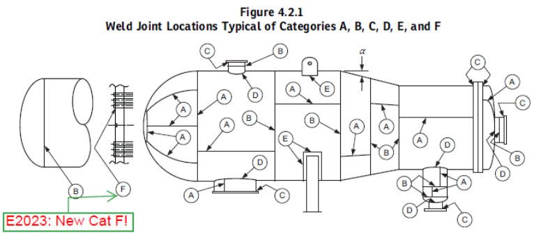
Below are changes with addition of Category F in 2023 edition of ASME Section VIII Div 1. Category F is for Tube-to-Tubehsheet welds. Interesting that also for Division 1 Heat Exchangers now the design rules are in Division 2, not the weld categorization.
According to ASME, while selecting the welding electrode, its strength should be considered and must be greater than or equal to the strength of the base metal.
If this is ensured, the design should take into account the weakest link, which is the base metal.
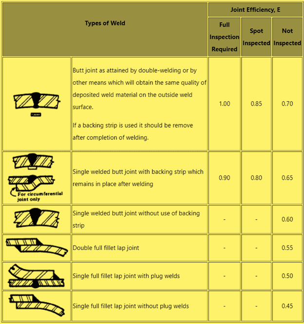
ASME provides statistical values for this parameter in Table UW-12 based on the type of joint and the level of inspection.
The efficiency of the joint is dependent on the type of weld joint and the level of non-destructive testing (NDT) conducted.
Joint efficiency depends upon the type of weld joint and extent of the NDT.
Weld joint efficiency factor table
A summary of welding joint types, and NDT scope defining the various joint efficiencies according to ASME BPVC Section VIII Div. 1 is shown in below Welding joint efficiency factor table.
Type of Joint
The choice of weld type, such as a butt or lap joint, is determined by the location of the joint and any service restrictions.
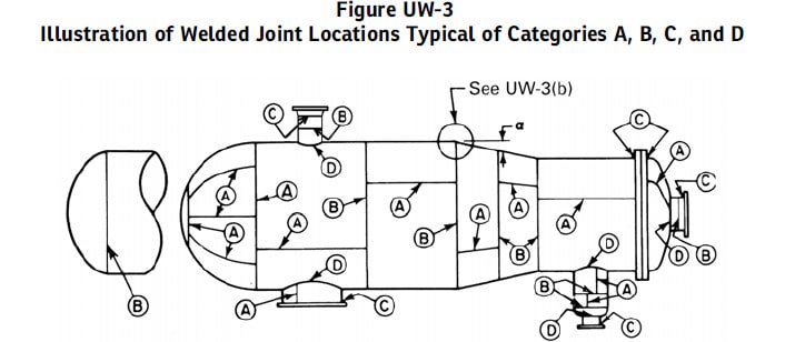
The location of joints in equipment is divided into categories as described in UW-3 and illustrated in Figure UW-3.
For example, longitudinal joints fall under category A, circumferential joints fall under category B, welds in a welded neck flange fall under category C, and welds connecting nozzles to shells fall under category D.
Service restrictions include potential hazards, temperature, pressure, and direct firing. Based on the service and joint category, the joint type selection is limited in UW-2.
This restriction should provide the optimal option against the expected types of stresses. ASME Table UW-12 includes the following joint types:
Butt Joint – Double Welding
Butt Joint – Single Welding without backing strip
Butt Joint – Single Welding with backing strip
Lap Joint – Double Fillet
Lap Joint – Single Fillet with Plug Welds
Lap Joint – Single Fillet without Plug Welds
Corner Joint
Angle Joint
Extent of Radiography
In certain situations, it can be unfeasible to conduct radiography on the entire length of welded joints.
As a result, ASME provides a criterion in UW-11 for determining whether to perform full radiography, spot radiography, or no radiography at all.
Full radiography means that the entire length of the welded joints will be inspected using radiography.
Spot radiography involves examining a small number of representative spots of the weld to represent the entire weld.
The level of examination is chosen in UW-11 based on factors such as:
Type of joint
Lethality of fluid
Thickness of joint
Design pressure
Type of Welding, for thick plates (Electrogas/Electroslag)
When spot radiography is allowed, according to UW-52, at least one spot must be examined for each 50ft section of weld length.
The length of each spot should be at least 6 inches, and at least one spot per section per welder should be examined to represent the weld quality of each welder.
Regardless of the number, the spots are recorded as a representation of the weld quality of the 50ft weld section. If the spot is accepted, then the represented weld section is also accepted.
If not, then two additional spots must be examined. If both additional spots are accepted, then the entire section is accepted, but the rejected spot still needs to be repaired.
On the other hand, if any of the additional spots are rejected, then the entire section is rejected.
The fabricator has two options, either the whole rejected weld section needs to be removed and welded again, or to be fully examined and repaired at the defective locations only.
Additionally, ultrasonic testing can be used instead of radiography if the material thickness is equal to or greater than 1/4 inch, and the same rules apply.
Joint Efficiency in ASME Section VIII
After determining the appropriate type of joint and level of examination, the joint efficiency can be obtained from Table UW-12 as previously mentioned.
It can be observed in the table that certain types of joints, such as fillet and angle joints, are not suitable for radiography.
This is due to the geometry of their arrangement, as the varying thickness of metal can make it difficult to interpret the radiography imagery.
Furthermore, these types of joints are typically designed for components that are under low loading, and are therefore considered non-critical, and not worth the resources required to examine them.
What is weld joint efficiency?
between two parts of a structure. It represents the fraction of the strength of the base material that is being utilized in the joint.
A joint with 100% efficiency means that the joint is able to transfer the full strength of the base material, while a joint with 50% efficiency means that the joint is only able to transfer half of the strength of the base material.
Weld joint efficiency factor
The weld joint efficiency factor is a term used to describe the portion of the strength of a welded joint that is utilized in a structure. It is often used as a factor in determining the allowable stress for a welded joint.
The joint efficiency factor is applied to the strength of the base metal, which is determined from the specified minimum tensile strength and the specified minimum yield strength of the base metal.
For example, the joint efficiency factor for a full-penetration fillet weld in a structural steel member is typically considered to be 0.75 or 75%. This means that the joint is able to transfer 75% of the strength of the base metal.
It’s worth noting that the joint efficiency factor is a conservative estimate of the strength of a welded joint and that the actual strength of a welded joint may be greater than the joint efficiency factor.
Therefore, the joint efficiency factor should be used only as a conservative estimate of the strength of a welded joint.
Joint efficiency of welded pipe
The joint efficiency of welded pipe is a measure of how well the welded joint transfers load between two sections of the pipe.
It represents the fraction of the strength of the base material that is being utilized in the joint.
A joint with 100% efficiency means that the joint is able to transfer the full strength of the base material, while a joint with 50% efficiency means that the joint is only able to transfer half of the strength of the base material.
For example, the joint efficiency factor for a full-penetration butt weld in a pipe is typically considered to be 1.0 or 100%, meaning that the joint is able to transfer the full strength of the base material.
It’s important to note that the actual strength of a welded pipe joint may be greater than the joint efficiency factor.
What is maximum value of weld joint efficiency in pressure vessel?
The maximum value of weld joint efficiency in pressure vessels is typically determined by the codes and standards that apply to the specific industry and application.
The American Society of Mechanical Engineers (ASME) Boiler and Pressure Vessel Code (BPVC) and the American Petroleum Institute (API) codes are two commonly used codes for pressure vessels that provide guidelines for determining the maximum value of weld joint efficiency.
According to the ASME BPVC, the maximum value of weld joint efficiency for pressure vessels is typically 1.0 or 100%.
This means that the weld joint is able to transfer the full strength of the base material. This applies to pressure vessels made of carbon and low alloy steels.
The API codes, on the other hand, have a maximum joint efficiency of 0.85 or 85% for pressure vessels made of carbon and alloy steels.
Material Welding is run by highly experienced welding engineers, welding trainers & ASNT NDT Level III bloggers.
We strive to provide most accurate and practical knowledge in welding, metallurgy, NDT and Engineering domains.