Welding Blueprints
Welding is a critical process in the construction of many metal objects. Blueprints are necessary to ensure that the welds are properly placed and spaced.
As a welder, it is important to be able to interpret welding blueprints and understand welding symbols and apply the information from them to the welding.
This will ensure that the welding job is done correctly and is of the highest quality. Welding blueprints in the drawings show how a weld should be made and where it should be made.
They can be used for both simple and complex welds. The blueprint will show the dimensions of the weld, the type of the weld, what type of welding process should be used, and any other special instructions.
Basics of Welding Blueprints
The American Welding Society’s (AWS) A2.4 standard specifies the requirements for welding blueprints.
The AWS A2.4 standard also includes guidance on how to create welding symbols, different types of welding symbols, and how to read them.
In summary, a simple welding blueprint looks like this:
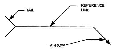
It consists of the following mandatory three parts to make a complete welding symbol:
- Arrow Line: Point towards the welding location,
- Reference Line: Horizontal line for placing weld symbol & size,
- Weld Symbol: Geometrical representation of weld type.
- Reference Line: Horizontal line for placing weld symbol & size,
A Complete welding symbol or welding blueprint for an actual job is shown below that includes all above three elements.

You will notice here different types of welding symbols. The question is: How you can tell what all of these means?
To interpret these symbols you need to know their meanings, types, and what they represent. Check out my this earlier article on How to read Welding Symbol? Here you will find all information from the basic to expert level.
Reading Welding Blueprints
The first step in correctly interpreting a welding symbol is to identify the basic elements of the symbol.
The arrow always points toward the weld location. The reference line is connected to the arrow line and weld symbols are placed on it. The weld size is always placed on the left side of the symbol.
The tail of the arrow contains information about the type of joint that is to be welded.
Types of Welding Symbols
Welding symbols are a crucial part of every welder. They provide a quick and easy way to communicate the details of a weld, including the type of weld, size, angle, and other important information.
There are three primary types of welding symbols specified in the American Welding Society’s standard AWS A2.4:
- Primary,
- Supplementary, and
- Contour weld symbols.
Primary welding symbols are used to indicate the most essential information about a weld, such as its type and size.

Supplementary symbols provide additional information about a weld, such as its angle or contour. Contour weld symbols are used to show the shape of a weld bead on a drawing.


Each type of welding symbol has its own set of rules and guidelines for use. When used correctly, they can save time and confusion in the shop or on the job site.
Fillet Welding Symbol
Fillet welding symbols are used to indicate the size, shape, and location of a fillet weld. You can notice a fillet weld symbol on a welding blueprint represented by a Triangle placed on the reference line.
There are two types of fillet welds:
- Full, and
- Intermittent.


Full fillet welds are used when both pieces of metal are to be joined along their entire length. Intermittent fillet welds are used when the two pieces need to be joined in multiple places along their length.
The weld size is always placed on the left side of a fillet weld symbol. center-to-center distance or fillet weld length is specified on the right side of the welding blueprint.
Groove Welding Symbol
In welding, the term “groove” refers to a V-shaped, J-shaped or U-shaped indentation in the metal. The most common type of groove weld is the V-groove weld, which is made by creating a V-shaped bevel profile on the joining member.
Read my article on Groove Welding Symbols and their types.
The size, shape, and location of the groove weld symbol indicate the type of joint that is to be welded.
The length and width of the root opening, as well as the angle of the sides of the V, are all specified on the drawing.
In addition, there are different symbols for partial penetration and full penetration groove welds.
Field/ Site Welding Blueprint
Welding is a critical process in the construction of any structure. A welder must have a clear understanding of the welding symbols used on blueprints in order to properly execute the weld.
He/ She must know what welding to be carried out in the workshop and which one at the final assembly site.
A Field or site welding symbol provides this information to the welder. Any welding symbol that shows a flag at the junction of the arrow line and reference line is to be made at the site as shown in the below figure.

Here, the CJP weld is to be made at the site while the 1/4-inch fillet weld has to be made in the workshop. A welder who is able to interpret this information will ensure that the right weld is placed in the workshop to avoid any rework.
Plug and Slot Weld Symbols
The permanent joining of metals by welding is a widely used and accepted method in today’s industry.
Plug Welds and Slot welds are easy-to-make welds used in all types of industries. Knowing and being able to interpret what plug or slot weld means, matters a lot for the right weld quality.

While plug welds are round the slot welds are elongated welds made to join two members of faying surfaces.
Material Welding is run by highly experienced welding engineers, welding trainers & ASNT NDT Level III bloggers.
We strive to provide most accurate and practical knowledge in welding, metallurgy, NDT and Engineering domains.