What is Partial Penetration Weld?
Partial Penetration Weld (PPW) or also called PJP (Partial Joint penetration) is a type of welding where the weld metal does not completely penetrate through the thickness of the base metal (weld joint) resulting in an incomplete penetration allowed by design.
This type of welding is typically used for joints that do not require full penetration or when the thickness of the base metal is too great for full penetration.
Partial Penetration Weld Symbol
Partial Penetration Weld Symbol varied based on the applicable code or standards such as AWS A2.4 vs ISO 2553.
In case of AWS A2.4, a partial penetration weld joint is specified”
- By providing a weld size smaller than the base metal, or
- by additional information in the tail section as “PJP” weld.

The weld preparation can be “V’ or “J” or “U” type, for example. The weld size will be specified on the left side of the weld symbol as shown in the below example.

The symbol for a Partial Penetration Weld (PPW) made of a reference line that is perpendicular to the base metal with an arrow pointing towards the side of the joint that is being welded.
A weld symbol. e.g., “V” or “U” shaped is added to the reference line specifying the weld size which is less than the plate thickness to indicate that the weld is only partial penetration.
This symbol is commonly used in welding blueprints and engineering drawings to specify that a PPW is required in a particular location.
Partial penetration weld symbol UK
Partial penetration weld symbols for UK are defined as BS 2553 standard.
In a partial penetration welding symbol, weld size “s” is specified on the left side of the weld symbol. if “h” is added, it refers to the depth of the groove.

Usually combination of letter “h” and “s” are used in a partial penetration welding symbol.
Read more: Welding Symbols in UK.
Partial Penetration weld Throat
Partial Penetration weld Throat (designated by letter “s”) refers to the depth of fusion in a welding joint, where only a portion of the welding material penetrates into the base metal.
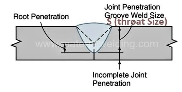
This type of welding is used for joints where the full penetration is not required, for example in thin plates or when access to the backside of the joint is limited.
The thickness of the partially penetrated material defines the size of the weld throat, which can affect the strength of the joint.
Remember that the throat size in a partial penetration weld is always smaller than the base metal thickness.
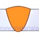
Partial penetration groove weld
A Partial Penetration Groove Weld is a type of welding where the weld metal only partially fills the groove between two pieces of base metal.
This type of welding is used when the thickness of the base metal is too great for full penetration or when the joint does not require full penetration.
Partial penetration butt weld
A Partial Penetration Butt Weld is a type of welding joint where the fusion between the two pieces of metal being joined does not go all the way through the thickness of the material.

The thickness of the partially penetrated material determines the size of the weld throat, which can impact the strength of the joint. Partial penetration butt welds are commonly used in the construction and manufacturing industries.
Partial joint penetration weld design example
Clause 4.7.2 of BS EN 1993-1 design standard covers Partial Penetration Butt Welds, directing the designer to use the method for a deep weld penetration fillet specified in Clause 4.5.2(3).
However, Clause 4.5.2(3) only defines the throat and does not provide guidance on how to calculate the design resistance.
Partial penetration welds are considered less ductile compared to full penetration welds and therefore, many design standards treat them similarly to fillet welds.
This is the reason behind the guidance provided in Clause 4.7.2. If rotation is not properly restricted, eccentricity must be considered when determining the stress in the weld.
BS EN 1993-1-8, Figure 4.9 shows details of partial penetration butt welds where eccentricity is present.
Partial penetration weld calculation
The calculation of partial penetration weld size as per AWS D1.1 code involves determining the required throat thickness based on the applied loads and the strength of the base metal.
To perform the calculation, the following steps can be followed:
- Determine the design loads and the strength of the base metal.
- Determine the minimum required throat thickness based on the applied loads and the strength of the base metal.
- Choose a welding filler metal that meets the minimum required throat thickness and has appropriate mechanical properties.
- Determine the appropriate welding procedure based on the chosen filler metal and the material thickness.
- Calculate the size of the weld based on the welding procedure and the thickness of the base metal.
The size of the partial penetration weld depends on the design requirements, the thickness of the base metal, and the properties of the filler metal used. The calculation should be performed by a qualified welding engineer or inspector, and should be verified by destructive testing if necessary.
Full penetration weld vs partial penetration weld
| Full Penetration Weld | Partial Penetration Weld |
|---|---|
| Complete fusion between base metals | Partial fusion between base metals |
| Stronger joint compared to partial penetration | Weak joint compared to full penetration |
| Used in high-stress applications | Used in low-stress applications or in situations where access to the back of the joint is limited |
| Usually requires complete access to both sides of the joint. | Only requires access to one side of the joint |
| Generally used in thicker plates | Generally used in thinner plates |

Dr. Sandeep Kumar
Hi, I'm Dr. Sandeep Kumar. I am a passionate Welding & Material Expert with a Ph.D. and M.Sc. in Welding Engineering. As an International Welding Engineer (IWE), I bridge the gap between academic research and practical industrial application. My goal is to share high-level knowledge on metallurgy, welding technical knowledge, and engineering best practices to help professionals and students succeed in the field.