Welding symbols are used to specify various aspects of a welding joint, including the type of weld, size, and location.
In the United Kingdom, welding symbols are in accordance with the BS EN 22553 standard which is similar to ISO 2553.
The standard specifies the general rules for the indication of welding on drawings, including the layout, dimensions, and symbols for welding, brazing, and thermal cutting processes.
BS 22553 Welding symbols Parts
BS EN 22553 “Welding symbols on drawings” describes the use of various lines and symbols to indicate the type, size, location, and other details of a welded joint.
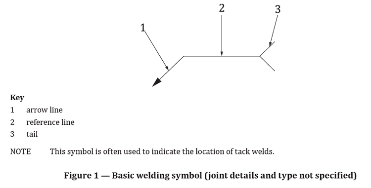
The main parts of a welding symbol are the arrow line, reference line, and tail. In summary:
Arrow line: The arrow line points to the location of the weld on the drawing. It is a solid line that originates from the reference line and points to the joint that is to be welded.
Reference line: The reference line is a horizontal line that runs parallel to the joint and is used as a reference for the location of the weld. It includes the symbol for the type of weld, the size and weld length.
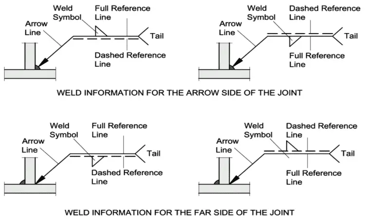
Dotted line: A dotted line is used to indicate the other side of the joint. It runs parallel to the reference line and is located below the joint.
Tail: The tail is located below the reference line and contains information about the type of weld, size, and any other relevant details.
Primary Welding Symbol UK
The primary welding symbols used in accordance with the BS EN 22553 standard in UK are:
BS ISO 2553 Arrow Side and other Side Welding Symbol Meaning
In the BS ISO 2553 standard, the welding symbols used to indicate the type, size, location, and other details of a welded joint.
The arrow side and other side symbols are used to specify the location of the weld on the drawing.
Arrow side: The arrow side symbol is used to indicate the side of the joint where the arrow line is pointing. So, if the weld symbol is placed on the solid reference line, welding will be on the arrow side.
Other side: The other side symbol is used to indicate the opposite side of the joint from the arrow line. So, if the weld symbol is placed on the dotted reference line, welding will be on the other side.
For example, if the arrow line is pointing to the left side of the joint, the arrow side symbol will be located on the left side and the other side symbol will be located on the right side of the joint.
Additionally, the symbol for the type of weld, size, and any other specifications such as the type of metal or the welding process to be used are specified on the tail of the welding symbol.
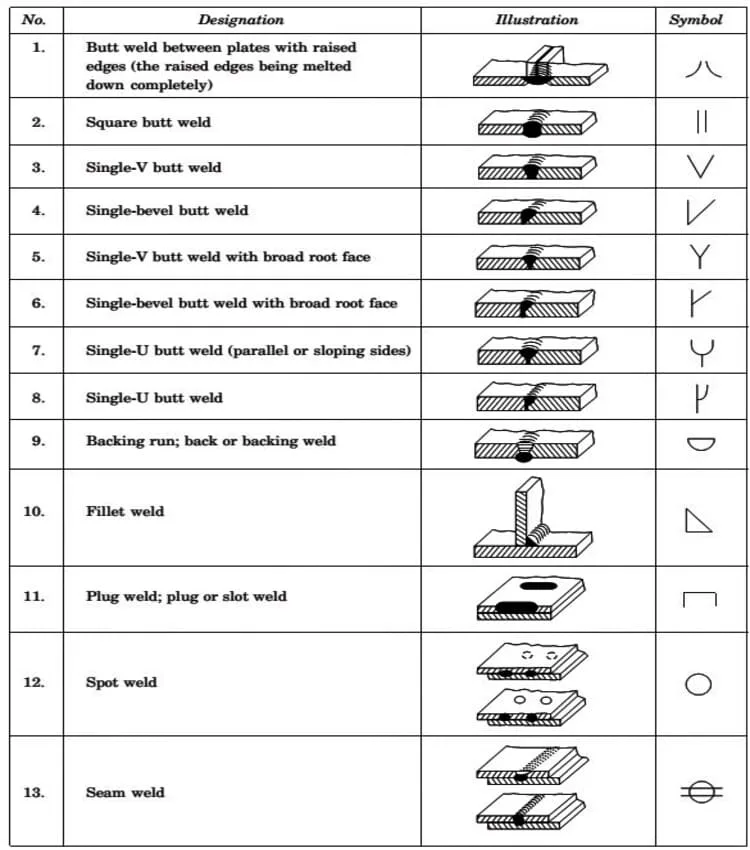
BS 22553 (BS ISO 2553) Fillet Weld Symbol
The fillet weld symbol is used to indicate a fillet weld on a drawing. A fillet weld is a type of weld that is used to join two pieces of metal at a 90-degree angle.
The symbol for a fillet weld is a triangular shape.
The weld size is placed always on left side of the weld symbol (triangular shape). In UK, weld sizes are given by fillet weld throat size (a) mostly.
Leg length dimension if used for weld size is represented by “z” (e.g., Z8 in below example).
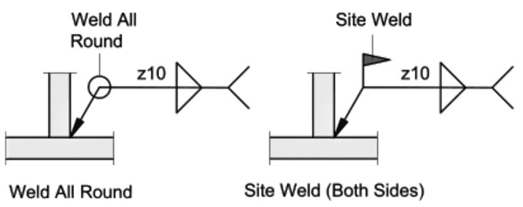
All-around symbol: The all-around symbol is used to indicate that a weld is to be made completely around the perimeter of a joint. It is represented by a circle around the welding symbol.
Site-weld symbol: In welding symbols, “site weld symbol” is used to indicate that the welding will be performed on the location where the assembly of the structure will take place and not in the fabrication shop. This means that the welding will be done on the final location of the structure, usually in a field.
The site symbol is represented by a flag above the arrow line and on the same side as the arrow line.
The flag symbol indicates that the welding is to be performed on site and not in the fabrication shop.
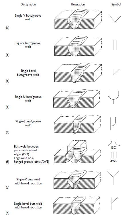
BS 2553 Groove Weld Symbols
In BS EN 2553 standard, the groove weld symbol is used to indicate a groove weld on a drawing.
The groove weld symbol is represented by a “V” shape. The size of the groove is represented by a size given on the left side of groove weld symbol. The dimension is written in millimeters (mm) or inches.
Additionally, the tail of the symbol may also include additional information such as the type of metal to be used, the welding process, and any other specifications.
There are several types of groove welds, each with a specific symbol:
Square groove weld is represented by a square or rectangle shape.
Bevel groove weld is represented by a “V” shape with a diagonal line across the legs of the “V”.
J-groove weld is represented by a “J” shape.
U-groove weld is represented by a “U” shape.
Flare-V groove weld is represented by a “V” shape with a curved line across the legs of the “V”.
Flare-bevel groove weld is represented by a “V” shape with a diagonal line and a curved line across the legs of the “V”.
Each type of groove weld has a specific symbol and dimension to indicate the size and shape of the groove as shown in below figure.
Material Welding is run by highly experienced welding engineers, welding trainers & ASNT NDT Level III bloggers.
We strive to provide most accurate and practical knowledge in welding, metallurgy, NDT and Engineering domains.


")


")