Strength calculations refer to the process of determining the ability of a material or structure to withstand various loads or forces without breaking or deforming excessively.
These calculations are typically done using mathematical formulas and principles of mechanics, and take into account factors such as the properties of the material, the geometry of the structure, and the type and magnitude of the loads.
The results of strength calculations can be used to design and engineer safe and reliable structures and products. A strength calculation is necessary, among other things, in mechanical engineering and architecture. These calculations are used to determine how strong or weak certain elements can be stressed and whether they can withstand the planned load.
In this way, components can be optimized and designs can be developed that can withstand the planned stress. In addition, optimizations can be carried out and the safety of constructions can be guaranteed.
What is Strength of Materials?
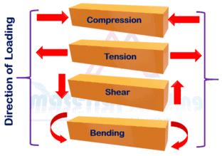
Strength of materials is the ability of a material or structure to withstand loads without breaking or deforming excessively. It is the study of how materials respond to external forces such as tension, compression, torsion, and bending.
It deals with the behavior of solid objects under stress and strain and the relationship between the external loads applied to a material or structure and the internal stresses and strains that result.
The goal of strength of materials is to understand how materials behave under different loads and to use this knowledge to design and engineer safe, reliable, and efficient structures and products that can withstand the loads to which they will be subjected in their intended use.
How is a strength calculation carried out?
Strength calculations are used to determine the ability of a material or structure to withstand loads and forces without failure. For the calculation of strength, fundamentals and methods of technical mechanics and structural analysis are applied.
In the modern computer age, graphical methods are used for better illustration. There are several methods that can be used to carry out strength calculations, including hand calculations and the finite element method.
Hand calculations
Hand calculations method involves using mathematical equations and formulas to calculate the strength of a material or structure. It is typically used for simple structures, such as beams and columns, and involves calculating the stresses and strains in the material, as well as the safety factors for the structure.
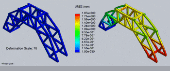
The Finite Element Method (FEM) is a numerical method that is used to analyze complex structures and materials. It involves breaking down a structure or material into a large number of small elements, each with known properties, and then using computer software to solve equations that describe the behavior of each element.
This method can be used to analyze structures under different loading conditions and to predict the response of the structure over time. The choice of method is based on the complexity of the system and the design requirements.
The hand calculations are used for simple systems and the FEM is used for complex systems, like aircrafts, bridges, or buildings.
Strength Calculations in Materials
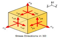
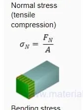
Calculation of Normal Stress in a Material
Stress is a measure of the internal forces within a material that resist external loads. It is calculated using the formula:
Stress = Force / Area
where Force is the external load applied to the material and Area is the cross-sectional area of the material.
The unit of stress is typically given in Pascals (Pa) or MegaPascals (MPa) or N/mm2 or pound per inch (psi) and Ksi.
For example, consider a cylindrical rod with a diameter of 10mm and a length of 100mm that is subjected to a tensile force of 200N. The cross-sectional area of the rod is:
Area = π * (5mm)2 = 78.5mm2
And the stress in the rod would be:
Stress = 200N / 78.5mm2 = 2.54 MPa.
Sample Strength Calculation
The strength calculation can be well illustrated by an example: A rod is used, which is loaded on both sides with the force F on tension.
This results in a stress σ (σ =F/A).
Assuming that the bar was made of S235 steel, the maximum stress corresponds σ the yield strength of 235 N/mm2. The aim is to find out whether permanent deformation can occur in this material. This should not be the case if the stress falls below the endurance limit.
For a cross-sectional area of, for example, 20mm2, the maximum force F is as follows:
This force F of 4700 N corresponds to a weight load of approximately 470 kg (on Earth).
Calculation of Normal Strain in a Material
Normal strain is a measure of how much a material has been stretched or compressed in a specific direction. It is calculated by taking the ratio of the change in length of a material to its original length. The resulting value is dimensionless and is often expressed as a percentage.
The formula for normal strain in a material is given by:
Strain = (change in length) / (original length)
For example, if a bar of steel has an original length of 10 meters and it is stretched to a length of 10.2 meters, the normal strain would be:
Strain = (10.2 – 10) / 10 = 0.02 or 2%
Note that strain is dimensionless and is often expressed as a percentage. In this case, the steel bar has undergone 2% strain.
Calculation of Shear Stress in a Material
Shear stress is a measure of the force exerted per unit area on a material when it is subjected to a shear force. The formula for calculating shear stress is:
Shear stress (τ) = Shear force (F) / Area (A)
For example, if a material is subjected to a shear force of 100 N and the area over which the force is applied is 10 cm2, the shear stress would be:
τ = 100 N / 10 cm2 = 10 N/cm2
Shear stress is calculated by dividing the shear force by the area over which the force is applied. The shear stress is measured in units of pressure, such as N/cm2 or Pa.
The higher the shear stress, the greater the force that is required to deform the material. It is important to note that the area used in the calculation should be the area that is perpendicular to the direction of the shear force, as the shear stress is only dependent on the area in that direction.
In practical engineering, shear stress is used to determine the strength and stability of structures, such as bridges and buildings, and the ability of materials to withstand deformation under load. In some cases, materials can withstand a higher shear stress than an equivalent tensile or compressive stress.
International standards for strength calculations
There are several international standards that are commonly used for strength calculations, including:
The Eurocodes are a set of international standards for the design of building and civil engineering works. These standards provide a consistent approach to structural design across Europe and include the following codes:
EN-1990 (Eurocode 0): This code provides the basis for structural design and includes general principles and requirements.
EN-1991 (Eurocode 1): This code covers the actions on structures, such as wind, snow, and earthquake loads, and how they should be taken into consideration in the design process.
EN-1992 (Eurocode 2): This code focuses on the design of concrete structures, including requirements for materials, structural elements, and fire resistance.
EN-1993 (Eurocode 3): This code covers the design of steel structures and includes requirements for materials, structural elements, and fire resistance.
EN-1994 (Eurocode 4): This code deals with the design of composite steel and concrete structures, including the interaction between the two materials.
EN-1995 (Eurocode 5): This code covers the design of timber structures, including requirements for materials and structural elements.
EN-1996 (Eurocode 6): This code focuses on the design of masonry structures, including requirements for materials and structural elements.
EN-1997 (Eurocode 7): This code covers the geotechnical design and includes requirements for soil mechanics and foundation design.
EN-1998 (Eurocode 8): This code deals with the design of structures for earthquake resistance, including requirements for materials, structural elements, and seismic analysis.
EN-1999 (Eurocode 9): This code covers the design of aluminium structures, including requirements for materials, structural elements, and fire resistance.
Offshore Design and Pressure vessels Standards
Offshore Design Standards are ISO 19900 series, DNV-GL, API & NORSOK standards.
Pressure vessels design codes are EN 13445 and ASME Section VIII Division I & II.
Material Welding is run by highly experienced welding engineers, welding trainers & ASNT NDT Level III bloggers.
We strive to provide most accurate and practical knowledge in welding, metallurgy, NDT and Engineering domains.


")


