What is a Fillet Weld?

Weld Fillet or Fillet Weld is a basic type of weld for welding two or three members using a ‘T’ joint, Lap joint, or Corner Joint configuration. Fillet Welds account for the bulk of weld type in every welding construction although they are not used for critical welding joints.
Fillet welds are not complete penetration welds (CJP Weld), and weld penetration is limited only to the root.
In a Weld Fillet, the plates or pipe or other material shapes are usually welded perpendicular to each other or overlapping plates (in the case of a lap joint).
One exception of skewed joint where fillet welds welded on members joined at an angle. Fillet Welds are easy to weld ad require the least welder skills.
Welding codes such as ASME Section IX or AWS D1.1 allows a welder who is qualified with a groove weld to weld fillet welds of any size on any material thickness.
What is a Weld Fillet Used For?
Fillet welds are the most predominately used type of weld in fabrication. They are easy to make as they do not need any particular welding joint preparation such as bevel making, root face & root gap preparation, etc.
Fillet welds are used for shear-loading applications or for providing strength to structures. Weld fillets are not applied in cases of load-bearing joints as they are not full penetration welds.
Fillet welds are subjected to limited non-destructive testing as they are not suitable for ultrasonic or radiographic Testing. Mostly penetrant testing and magnetic particle testing is used for fillet welds.
What is fillet Weld Sizes?
A Weld Fillet or Fillet Weld sizes are checked for either throat size (z) or leg length size (a). AWS Standards such as AWS D1.1 (the most famous welding code) or API or ASME or CSA (Canadian) codes use leg length of fillet weld measurements.
ISO/ British/ German/ Australian standards rely upon Fillet Weld Size measurements using the Throat Size (a).
Refer to the below figure & you will find many other important measurements that are used for Fillet Weld are as:

- Throat size (a), usually by measuring the actual throat of the fillet weld.
- Leg Length (z), there are two leg lengths of a fillet weld.
The leg Length of a Fillet Weld is referred to the vertical and horizontal length of the triangular shape of the fillet.
Similarly, the throat size (a) of a Fillet weld is the length of the altitude on the hypotenuse of this triangle.
Parts of A Fillet Weld
A Fillet weld is comprised of various elements. These elements or terms are shown in the below figure. The main parts of a Fillet Weld are:
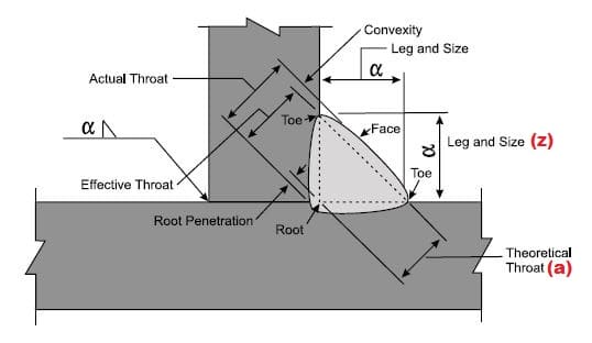
- Fillet Weld Throat (a)- Theoretical throat, actual throat & Effective throat.
- Fillet weld Leg Length (z)
- Weld’s face
- Weld Toe
- Root
- Root Penetration
- Fillet weld Convexity or concavity
Dimension of a Fillet Weld
Fillet weld is specified by a size known as either throat size (given as a) or leg length (given as z).
Throat size measurement is used in ISO & British inspection standards while leg length is used in AWS (Americans) & CSA (Canadian) welding inspection standards.
So how do you define the fillet weld size?
Weld Fillet Symbol (Fillet Weld Symbol)
The standard fillet weld symbol is represented by a right-angle triangle placed on the reference line.
The vertical side of this triangle showing the fillet weld symbol is always placed on the left side of the drawing reader/ viewer as shown in the below figure.

The fillet welds are placed either on the arrow side or other side. They can be welded on both sides two using a symmetrical welding symbol as shown above.
Placing Fillet Weld Size & Length in a Weld Symbol
Fillet weld size is always placed on the left side of the Fillet Weld Symbol as represented in the below example.
Similarly, the length of the fillet weld must be given on the right side of the Fillet Weld Symbol. If length is not specified, it means welding has to be deposited in the full length of this location.
Weld All Around Fillet Weld & Field Weld
A Weld All Around Fillet Weld Symbol is represented using a circle that is placed at the arrow line & the reference line junction as shown in the below example.

While a Field Weld Fillet Weld Symbol is illustrated using a flag (Can have any direction- left or right) although should be opposite to the arrow. Field Weld Symbol is also placed at the junction of the reference line & arrow line.
Apart from the above, Fillet Weld Symbol includes Supplementary Welding Symbols to show the weld contour.
Refer below figure & look at the various contours that apply to fillet weld based on general Fillet Weld Shape and artificial Fillet Weld Shape resulting due to mechanical means as:

- Concave Fillet weld Shape
- Convex Fillet weld Shape
- Flat or Mitre Fillet weld Shape
What are the Types of Fillet Welds?
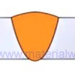
Fillet Weld Types are dependent on the weld appearance or the weld joint configuration. A Fillet weld has roughly a triangular shape & depending on the welding process & related variables can result in various face appearances. The main types of Fillet welds based on their shape and joint configuration are discussed here.
Fillet Weld Types Based on Appearance
Fillet welds are having a more or less triangular appearance that you can notice in a fillet weld cross-section sketch or fillet weld macro test. Based on weld shape, Weld Fillets are classified into three types:
- Convex Fillet Weld
- Concave Fillet Weld
- Miter Fillet Weld

Fillet Weld Types Based on Joint Configuration
A Fillet weld can be between two members placed at a right angle to each other as a corner joint or ‘T’ shape configuration or placed parallel to each other to form a lap joint as represented in the below figure.

So, considering the weld joint configuration, Fillet Welds are further classified as:
- lap joint Fillet Weld
- T- Joint Fillet Weld
- corner joint weld
Fillet Weld Strength
A Fillet Weld Strength is controlled & delivered by its leg Length (z) and Throat Size (a). The load is applied in a Fillet weld via the throat.
This is hence considered to be the critical element for Fillet weld Stress Calculation. They are subjected to shear stress on their throat.
Using a mathematical equation you can calculate the strength of a given Weld Fillet size.

Mathematically, there is a relation between the Fillet Weld Throat size (a) & leg Length (z). For a fillet weld with equal leg lengths, the cross-section triangle is a right-angle triangle with angles of 45 degrees in each corner.
The relationship between weld throat ‘a’, and leg length ‘z’ is given mathematically by:
a ≈ 0.7z and z ≈ 1.4 a
(For the maths-minded, 0.7 is 1/√2 and 1.4 is √2)
Material Welding is run by highly experienced welding engineers, welding trainers & ASNT NDT Level III bloggers.
We strive to provide most accurate and practical knowledge in welding, metallurgy, NDT and Engineering domains.