This post explains the steps for measuring fillet welds, gives the information about fillet weld, its types, techniques for weld measurements and different types of welding fillet gauges.
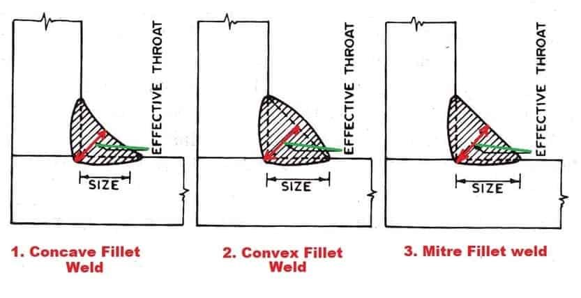
What is Fillet Weld?
Fillet Weld means the welding joint that occurs when two plates or other shapes are welded perpendicular/ or at an angle to each other.
The fillet weld appearance is triangular in shape and can have a concave, flat, or convex surface appearance depending on the welder’s technique and welding parameters.
Based on these appearances, the fillet welds are having following types:
Concave fillet,
Convex fillet, and
Mitre weld.
What is Concave fillet Weld?
A concave fillet weld is a type of weld where the face profile dips inward and the throat size is smaller than leg length. This type of weld is good for cyclic loading, as it can withstand repeated stress without breaking.
The main advantage of a concave fillet weld is that it is very strong and can support heavy loads. However, concave fillet welds are more difficult to create than other types of welds, so they are not always the best choice for every application.
What is Convex fillet Weld?
Welders often strive to produce a convex fillet weld, as this type of weld face is typically seen as being more aesthetically pleasing than a concave weld face.
However, it is important to note that excessive convexity can actually have a negative impact on the overall strength of the weld, as it can create weld bumps that protrude outward from the surface.
As such, it is crucial to maintain control over the amount of convexity in order to ensure that the weld is strong enough to withstand any external loads.
Additionally, it should be noted that there is no added benefit to having an excessively convex weld; thus, welders should focus on creating a balance between aesthetics and functionality.
What is Mitre fillet Weld?
A mitre fillet weld is a weld with a triangular cross-section. It is strong but needs weld flushing to produce mitre weld. For special applications, it is used to join two pipes at an angle.
Fillet welds and predominately used weld joint types in construction, structural and general fabrication although they are not used in critical weld joint locations.
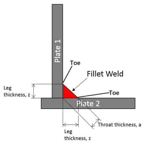
Throat size measurement is used in ISO & British inspection standards while leg length is used in AWS (Americans) & CSA (Canadian) welding inspection standards.
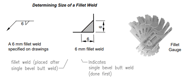
So how do you define the fillet weld size?
How to Measure Fillet Weld Size using Fillet Gauge?
Leg length measurement is used mainly in American, and Canadian codes & standards such as AWS D1.1, CSA W59 & ASME Codes.
Measurement of fillet using throat size is used mostly in ISO codes, BS, & EN standards (e.g. ISO 5817). So, an AWS-CWI welding inspector will measure welds using leg length (z) while a CSWIP or IWIP Inspectors will be taught to measure fillet welds using Throat size (a).
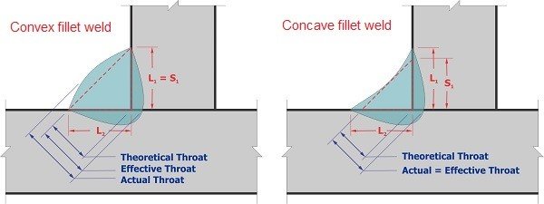
The figure shown above is a theoretical concept of a filler weld– represented by an equilateral triangle. You will notice that an actual fillet weld is difficult to achieve with this profile unless external grinding or machining is applied on the fillet weld surface.
The actual fillet weld will have either a convex or concave weld profile.
When we design fillet welds, the shear stress calculation is based on the throat size (a) of the fillet weld. we can convert leg size (z) to throat size (a) using the below simple equation:
a = z/√2
Click here to Learn How to find out the Minimum & Maximum size of a Fillet weld.
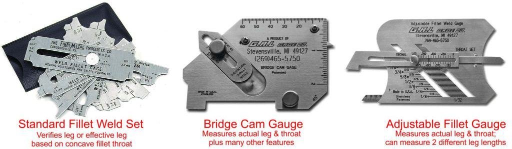
Welding Measurements: Measuring the Fillet Weld size using Fillet Gage
The leg length refers to the distance from the root to the toe and should be measured in both directions using fillet gauges. The fillet weld measurements are carried out using two approaches:
Measurement of the Leg Length: Where leg length (z) means the dimension from the root point to the weld toe. So, two leg lengths are there for fillet weld shown in the below figure as L1 & L2. These leg lengths are shown as usually as Z1 & Z2 in the code or standards.
Measurement of the throat size: Where throat (a) is the measurement from the deepest point of either the penetration (fillet weld) (usually based on a cross-section).
Fillet Welding Gauge Measurement
Weld joint fit-up and final welds are checked for the correct size, shape, reinforcement height, misalignment, and geometry with the help of pre-defined templates called FilletWeld Gauges.
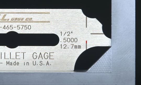
In AWS-CWI certifications measurements of a fillet weld are taught using the Standard Fillet weld gauge set for the most commonly used weld sizes, say 1/8 inch to 1 inch as shown in the below picture.
Here, each gauge has its cut for the maximum and minimum size of a given weld.
One side of the gauge is used for convex weld while another side is used for concave fillet weld.
Before measuring the welds using the fillet gauge- perform the visual inspection and decide the type of fillet weld for:
Concave weld or
convex weld
Flat fillet weld
Next, you should select the standard fillet gauge side to be used for the fillet weld size measurements.
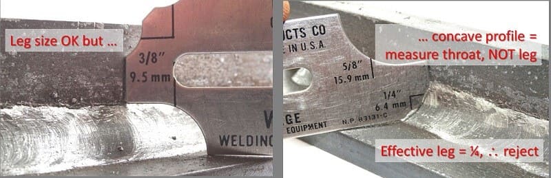
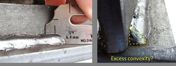
As you can see in the below picture, the weld appears to be convex size, hence the convex side of the gauge is used for the measurement. Here, the weld size (leg length) is 3/8 inch or 9.5 millimeters.
Fillet weld Leg length measurement & Inspection
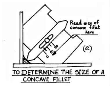
Considering other scenarios, where the weld appears to be concave, the weld size shall size be assessed using the other side of the weld gauge where the center tab is required to touch the weld face.
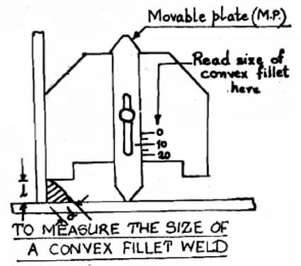
You can also use an Automatic fillet gauge for fillet weld Leg Length measurement & inspection as shown in the below picture.
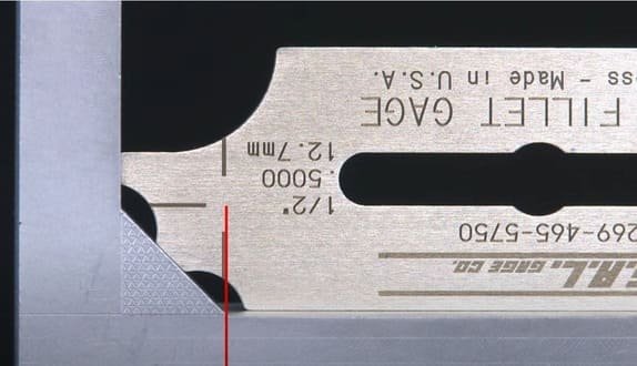
Here in this example a weld having the required leg length (z) is shown but the weld should be rejected due to excessive concavity resulting in reduced effective leg length.
The leg size is measured as 3/8 inch but using the concave size measurement, the effective weld size is 1/4 inch only.
The vertical black line (left side picture) visible on the gauge specifies the equivalent leg length in the horizontal direction for reference.
On the other case on the right-hand side, concave fillet weld measurement is shown.
The two black lines are visible on the gauge (right-hand side) point towards the effective weld toe of the imaginary triangle for the corresponding fillet weld based on the concave fillet.
Concave fillet weld measurement using an Automatic Fillet weld gauge is given in the below example.
Convex Fillet welding measurement is carried out using the fillet weld gauge by measuring the leg lengths (z). Fillets can have excessive convexity which could be the cause of weld rejection.
AWS D1.1 or ASME B31.3 are less stringent on excessive fillet weld convexity but ISO standards such as ISO 5817 are very stringent and define the rules for excessive convexity.
In the below first picture, the weld appears to be having a sufficient leg length size of 1/4 inch but checking the weld profile it is having high weld convexity.
High weld convexity, add the stress risers or also called notch effect on the fillet weld toe. These points could be the initiation points for weld failures and can crack the welding joint.
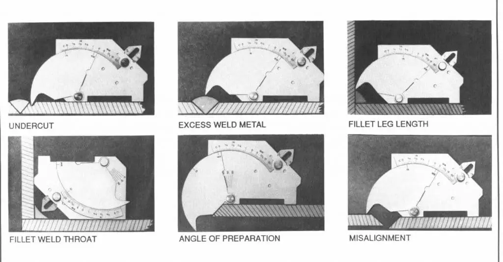
Bridge Cam gauge is a multi-purpose welding gauge used for welding measurements of fillet weld- leg length (z) & throat thickness (a), weld reinforcement height, depth of undercut, angle of bevel or preparation, and weld misalignment.
The bridge Cam gauge is also called the Cambridge gauge.
The Bridge Cam Gauge uses both imperial and metric scales for weld measurement.
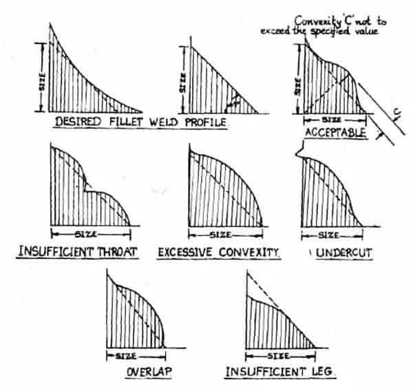
The weld visual of Fillet welds shall confirm the lack of any overlap, lack of fusion, porosity, excessive concavity/ convexity, excessive asymmetrical leg lengths, and free from cracks.
A details visual guide for different scenarios on Fillet Weld Profile application of weld visual inspection is given in the below example.
Fillet Weld Acceptance Criteria
The Visual Inspection criteria for Fillet Weld can be referred from AWS D1.1, Table 8.1 and Table 10.15 as well as in the ISO 5817 Standard. These two are the most used welding acceptance standards where you need detailed inspection guidelines.
Material Welding is run by highly experienced welding engineers, welding trainers & ASNT NDT Level III bloggers.
We strive to provide most accurate and practical knowledge in welding, metallurgy, NDT and Engineering domains.