Radiograph film interpretation for welds is an essential skill for any weld inspector. It enables inspectors to assess the quality of welds.
Radiographs are produced by using X-ray or gamma radiation to penetrate the material being tested and create an image which can be interpreted by a trained professional.
This article will provide a comprehensive overview of how to interpret radiograph films for welds.
Interpretation vs Evaluation in NDT
In Non-Destructive Testing (NDT), Interpretation and Evaluation refer to two distinct but related processes in the evaluation of test results.
Interpretation in NDT refers to the process of explaining the significance of the indications or readings obtained during a non-destructive examination.
It involves analyzing the information obtained from the test and presenting it in a meaningful and understandable manner, taking into account the type of test, the test equipment used, the conditions of the test, and the specifications and standards being followed.
Evaluation in NDT refers to the process of determining the acceptability or rejectability of the item based on the results of the non-destructive examination.
It involves assessing the indications or readings obtained during the test, comparing them to the relevant standards, and making a final judgment on the condition of the item being tested.
The evaluation process is critical in NDT as it provides the information needed to make informed decisions about the safety and serviceability of the item being tested.
In summary, Interpretation in NDT is the process of explaining the results of a non-destructive examination, while Evaluation is the process of determining the acceptability or rejectability of the item based on the results.
Factors affecting the interpretation of test results in Radiography
In Radiography, the interpretation of test results can be influenced by several factors, including:
Quality of the Radiographic Image: The quality of the radiographic image is a major factor affecting the interpretation of test results. Factors such as film quality, exposure conditions, and processing techniques can affect the clarity and resolution of the image, making it more difficult to accurately interpret the results.
Knowledge and Experience of the Interpreter: The knowledge and experience of the interpreter plays a crucial role in the interpretation of radiographic test results. A well-trained and experienced interpreter will be able to accurately identify and interpret the features and anomalies present in the image.
Radiographic Technique: The radiographic technique used can also impact the interpretation of test results. Factors such as film-screen combination, object-to-film distance, and radiation energy can affect the quality of the image and the interpretation of the results.
Type and Size of Defects: The type and size of the welding defects present in the item being examined can also impact the interpretation of test results. Some defects, such as cracks, are easier to detect and interpret, while others, such as porosity, can be more challenging to identify.
Use of Enhancement Techniques: The use of enhancement techniques, such as film and digital image processing, can also impact the interpretation of test results. These techniques can help to improve the clarity and visibility of the image, but they can also introduce artifacts and false indications that can affect the accuracy of the interpretation.
The interpretation of radiographic images of welds involves several steps, including:
1. Familiarization with the Specification: The interpreter should be familiar with the relevant welding specification and codes, such as AWS D1.1 or ASME Section IX, as they provide the acceptance criteria and standards for evaluating the radiographic images.
2. Review of the Radiographic Image: The interpreter should thoroughly review the radiographic image to become familiar with the details of the weld, including the size, shape, and orientation of the weld, the position of the weld relative to the film, and the presence of any anomalies or defects.
4. Comparison to Acceptance Criteria: The interpreter should compare the radiographic image to the relevant acceptance criteria and standards to determine whether the weld meets the required quality standards.
5. Documentation of Results: The interpreter should document the results of the radiographic interpretation, including a description of any defects or anomalies present in the weld, their location and size, and the evaluation of the weld against the acceptance criteria.
6. Final Conclusion: Based on the evaluation of the radiographic image, the interpreter should reach a final conclusion on the acceptability or rejectability of the weld, and provide recommendations for further action if needed.
Radiographic Indications on Welding
Radiographic indications are signs of potential problems or defects that can occur during the welding process. These indications can be detected using X-ray or radiographic imaging techniques, which provide a detailed and non-destructive view of the interior of the weld.
Some common radiographic indications in welding include:
Lack of Fusion (sidewall, interun and root)
Incomplete Penetration
Porosity
Crack
Slag Inclusion
Undercut
Overlap
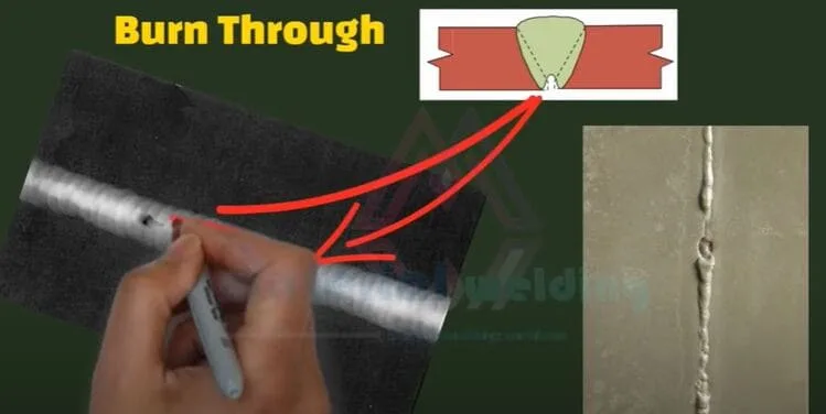
Burn-Through
Lamination
Burn through.
Radiography Film Interpretation for Welding Defects
Radiography film interpretation is the process of examining radiographic images to detect and evaluate welding defects.
Welding defects can be internal or external, and can affect the strength and integrity of the welded joint. Watch below video to learn how different welding defects appear on the radiography film.
In general, casting defects such as gas porosity, shrinkage cavities, and inclusions appear as darker areas on the radiography film, while cracks appear as linear discontinuities in the image.
The size, shape, and location of these features on the radiographic film can provide important information about the nature and severity of the defect.
For example, large and irregularly shaped dark areas on the film may indicate the presence of gas porosity, while small, round or elliptical areas may indicate shrinkage cavities.
Linear features that extend through the entire thickness of the casting may indicate cracks, while those that are confined to a specific region may indicate inclusions.
Jiten Karmakar is an NDT Specialist, holding ASNT NDT Level III and ISO 9712 NDT Level III Qualifications. He is having vast hands-on practical and theoretical experience with all major NDT Methods and technique.


")


 Guide")

: Everything you need to know")
