Welding is a critical process in manufacturing & fabrication. Ensuring the right quality of welds is not only necessary for safety, but also for producing strong and reliable welding joints. In order to ensure that all welds are up to industry standards, weld inspection tools and techniques must be utilized.
There are several types of inspection tools used by inspectors which vary depending on the type of welding being done. Visual inspections can be conducted with naked eyes with visual aids such as mirrors or cameras, while other tools such as x-rays or ultrasonic testing can be used to detect internal flaws in the welds.
These tools and techniques help inspectors identify any issues with the welds before they become major problems that can lead to costly repairs or even shutdowns.
Selection of Suitable Method
Every inspection method and tool have its limitations. The inspector should understand these limitations in order to judge whether or not the proper methods are being used and used correctly.
Regardless of the tools used, it is important to check a percentage of each welder’s work and to determine whether each welder is making good welds.
Weld Inspection Methods: Procedures, Applications and Limitations
Visual Inspection
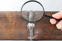
Visual inspection before and during welding is the single most effective method for eliminating and minimizing weld defects and repairs.
Visual inspection of completed welds is used to detect surface defects such as misalignment (high-low), undercut, overlap, surface cracks, craters, porosity, and poor workmanship as indicated by excessive weld spatter, irregular beads, high weld crown, arc strikes, etc.
A flashlight, a small extension mirror and a magnifying glass are valuable for close work, and for inspecting through small openings such as the ID of a pipe or boss.
The Borescope is an optical instrument that is particularly useful for looking at the hidden underside of a weld in a pipe or plate, where most defects are located.
By leaving a small gap or drilling a hole in the root pass, the back side may be inspected and, if necessary, repaired before completing the weld.
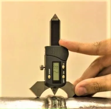
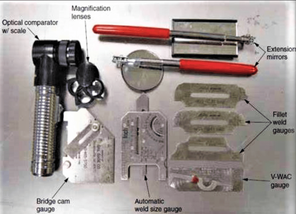
The main weld inspection tools used by welding inspectors are:
The Borescope is best suited for de tec ting lack of penetration, low root or concave root bead, excessive penetration and internal misalignment. This tool can save a lot of time, particularly on thick walls, and when welds must be radiographed after completion or stress relieved and then inspected for defects.
It may be necessary to cut out all or part of a weld to check a defect, especially if in doubt about a radiographic or ultrasonic indication.
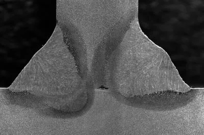
It is sometimes better to cut out the entire weld rather than gouging out the defective area because the complete cutout allows re-beveling for good fit-up. The other advantage of a cut-out is that it permits examination of the inside surface and of cross-sections.
Hole-saw trepanning cuts out a plug that provides a View of the weld cross-section and the underside of the weld. Trepanning should be discouraged because it leaves a hole in the work that is difficult to repair.
To show the weld outline including the individual passes and heat-affected zones, the section surfaces can be ground smooth, sanded free of scratches, and etched.
Two effective etching solutions are hot (about 160°F) one-to-one hydrochloric acid (muriatic) in water or ten percent ammonium persulfate in water. The hydrochloric acid solution is better for showing weld defects while the ammonium persulfate solution is better for showing weld outlines.
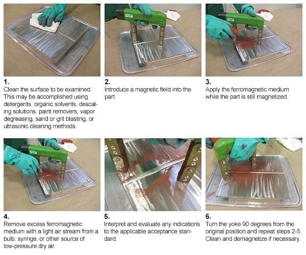
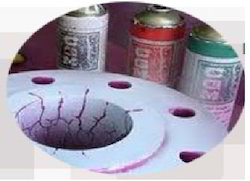
Magnetic Particle Inspection
The magnetic Particle Inspection technique is excellent for detecting fine surface and slightly sub-surface cracks in carbon and alloy steels, but cannot be used with austenitic stainless steels or non-ferrous alloys which are non-magnetic.
There are two common methods, dry powder (Magnaflux), and fluorescent particles. fluorescent uses ultraviolet light to illuminate the fluorescent particles. It is the most sensitive method but must be used in a darkened area.
The surface must be clean and dry in order to allow the magnetized particles to move freely and collect at defects.
During the inspection, check the part with a piece of steel such as a knife blade or a carbon steel weld rod, to be sure it is being magnetized. Higher amperage or closer prod spacing may be necessary.
For a full inspection, you must inspect with the magnetic field oriented in two directions, at 90° to each other.
The magnetic particle method is not reliable for sub-surface defects. Many sub-surface “cracks” in fillet welded Tee joints are normal root voids, and surface “cracks may be small weld undercuts. Don’t assume the technician’s interpretation is correct, but identify defects by close visual examination, grinding, acid etching, sectioning, radiography, etc.
The penetrant technique is useful for defects open to the surface which are too small to be seen by the eye and is particularly valuable for non-magnetic materials where the magnetic particle technique cannot be used.
Step III. Remove excess penetrant, clean with solvent and spray on the developer.
The solvent, dye penetrant, and developer are available in aerosol cans. The surface must be thoroughly cleaned with the solvent to permit the penetrant to get into the defects.
For best results, the metal should be warmed slightly (90°F to 109°F) before spraying with dye penetrant when performing dye penetrant in cold climates or sub-zero temperatures.
If it is overheated (above 120°F) the penetrant in any defects may dry up, thereby ruining the test.
Allow 5-15 minutes for the penetrant to soak into cracks. After removing excess penetrant and spraying on the developer, examine the surface immediately for indications of defects.
Excepting very small or tight cracks, the true size and shape of the defect is best defined in the first few seconds after the developer is applied. Check again after 15-20 minutes for any small defects which might have appeared subsequently.
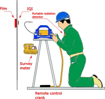
Radiography (X-ray and Gamma Ray)
Radiography is usually a contract service and is performed by technicians of varying abilities and attitudes. The inspector must see that the technicians take pictures of good quality and that the interpretations are correct.
Films that are not properly exposed and processed to show the weld image clearly should be rejected.
Poor RT images are most likely to be caused by one or more of the following:
(1) Use of a coarse-grained film and/or fluorescent screens, resulting in poor contrast and poor definition or sharpness of the image.
(2) Wrong size or poor placement of the radiographic source resulting in a lack of definition or sharpness.
(3) Using the wrong penetrameter or using it incorrectly. Check the sharpness of the weld image; both the weld image and the penetrameter image should be sharp. If the penetrameter shows clearly but the weld image is fuzzy, either the wrong penetrameter was used, it was not shimmed up sufficiently, or it was placed on the film side rather than on the source side of the weld. (For most piping radiography the penetrameter can only be placed on the film side.)
(4) Poor film processing (dirty water, spent chemicals, high or low bath temperatures, under exposing and overdeveloping will cause poor contrast and definition, grainy films, chemical stains, and streaks. Damaged or dirty lead screens produce false indications on the film.
(5) Careless handling of film can produce static marks, scratches and other indications which may be confusing.
(6) Refer to the sample films for the appearance of typical weld defects and film quality.
Ultrasonic Inspection (UT)
Perhaps even more than radiography, the UT technique involves the use of very special equipment and training. Its proper use depends primarily on the skill and integrity of the UT operator.
On highly critical work, obtain technical assistance to verify the UT technique, the ability of the operator, and the interpretation of defects. If possible, check the operator by testing him on sample welds containing defects of known type and severity.
UT is most valuable for rapid inspection of production work for gross defects. Use radiography to verify the type and severity of the defect indicated by UT.
Hardness Test
One use of the hardness test is to determine if a hardenable low-alloy steel weld has been adequately post-weld heat treated and is within specified hardness limits.
For field use, the most reliable hardness testing instruments are the King Brinell, the Portable Brinell Meter, and the Telebrineller. Spring-loaded instruments such as the Ernst hardness tester are generally erratic and should not be used.
Grind or file the spot to be tested flat and smooth. For accurate measurement a true circular indentation is necessary.
Material Welding is run by highly experienced welding engineers, welding trainers & ASNT NDT Level III bloggers.
We strive to provide most accurate and practical knowledge in welding, metallurgy, NDT and Engineering domains.

")


