The various methods used for the severing or removal of metals can be divided into two main categories:
Mechanical Cutting and
Thermal Cutting.
Mechanical methods are sawing, drilling, shaping, milling, etc., commonly used in metalworking and machine shops. Thermal cutting methods involve heat to melt or ionize the material to remove it. The most commonly used thermal cutting processes are:
Oxyfuel cutting or flame cutting (OFW)
Metal arc cutting, e.g., gouging
Plasma cutting
Electron beam cutting
Laser Cutting
Spark erosion cutting (EDM)
What is a Plasma Arc?
Plasma as you may know is the 4th state of matter after liquid, solid & gas. The plasma is defined as a highly ionized electrically conducting column of gas (e.g. oxygen, argon, or nitrogen) that results due to the heating of these gases to a very high temperature.
The plasma jet in any arc results from magnetic constriction of this conducting plasma column that is called Plasma Arc.
Cheapest Plasma Cutter
When it comes to finding the best & cheapest plasma cutter, there is no shortage of options on the market. But if you’re looking for the cheapest plasma cutter, that can be a bit more difficult. The good news is that there are some great options out there, even if they might not be the absolute cheapest.
One of the best budget-friendly plasma cutters on the market is the Yes Welder CUT55DS Plasma Cutter. This machine offers a lot of features for its price point, including an impressive IGBT output and a handy torch cable.
It’s also very easy to use, making it a great option for beginners or those who don’t have a lot of experience with plasma cutters.
Another great option for those looking for a low-cost plasma cutter is the Hobart Airforce 12Ci & Primeweld CUT60.
What is Plasma Cutting?
Plasma arc cutting is defined as the Cutting with a plasma arc in which the constricted arc (having a temperature of more than 20,000°C) melts a narrow region of metal which is then blown away by the force of the arc.
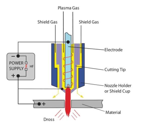
The material to be cut is placed at the positive terminal (anode) and the electrode on the negative terminal (Cathode) to generate an electric arc.
The important characteristics of plasma cutting are the melting of the metal by a high thermal intensity plasma arc and the removal of the molten material by the high-velocity gas jet. Unlike oxygen cutting, no exothermic reaction is required to sustain the process.
Plasma Cutting Machine Working Principle
The plasma Cutting machine is designed in the same manner as the plasma arc welding torch. Direct Current (DC) is used in Plasma Cutting and the tungsten electrode is connected to the negative pole, called Cathode. The material to be cut is attached to the positive pole or also called Anode.
A transferred arc is employed for cutting, i.e., the arc is sustained between the electrode in the torch (Cathode) and the work (Anode). The cutting arc is initiated by a pilot arc, which is first formed between the electrode and the constricting nozzle by the high-frequency generator.
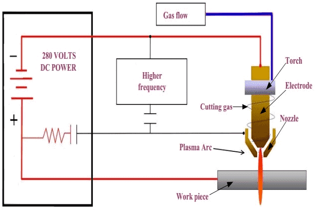
The constricting nozzle, which is water-cooled, is connected to the positive terminal of the power source through a current limiting resistor and a pilot arc relay contact. The simple Plasma Arc Cutting circuitry is shown in the below figure.
In a single flow Plasma Arc Cutting torch, i.e., a torch that provides for the flow of orifice gas and not of shielding gas. The orifice gas, which is preheated by the arc plasma, expands and is ejected through the constricting orifice at a high velocity.
The metal which is melted by the arc is then blown away by the kinetic energy of the gas stream to form the kerf. The orifice gas is usually argon.
In a dual-flow torch (shown in the above figure) provision is made for the flow of secondary shielding gas around the arc plasma. In this case, the usual orifice gas is nitrogen.
The shielding gas is carbon dioxide in the case of mild steel and stainless steel, and argon-hydrogen mixture in the case of aluminum and its alloys.
The technique can be modified by using water as a shield in place of the auxiliary shielding gas. In either case, the cut quality is not as good as when a single-flow technique is used.
Water Injection Plasma Cutting
The most efficient system of Plasma Arc Cutting which is capable of giving narrow, sharply defined cuts at high speeds involves the injection of water into the plasma flame to further constrict it and to prevent the plasma from turbulent mixing with the surrounding air. This process is termed water injection plasma cutting.
Plasma Arc Cutting Machine Setup
The power sources for plasma cutting are usually integrated DC systems with arc starting, gas flow, and water-cooling systems built-in.
The high current, active plasma gases, and increased constriction lead to higher operating voltages which may be in the 50 to 60-volt range.
Drooping volt-amp characteristics are used and open-circuit voltages can be as high as 400 volts.
PAC equipment consists of a power source, a control unit, one or more gases to function as orifice and shielding gas, and a cutting torch.
It can be manual or mechanized. The power source is of drooping type, giving DC with open-circuit voltages in the range of 120-400 V and output current in the range of 70-1,000 amp. It may also contain the pilot arc and circuitry for a high-frequency generation.
For cutting ferrous material as thick as 75 mm and aluminum up to 90 mm, OCV of nearly 400 V and current up to 500 amp may be required.
Because of the inherent danger of electric shock to the operator, manual cutting equipment uses lower OCV of 120-200 V, and current in the range of 70-100 amp, and achieves relatively low cutting speeds.
Manual PAC can be used conveniently for cutting non-ferrous metals up to 25 mm thickness and carbon steel up to 12.5 mm thickness.
The control unit contains solenoid valves to turn gases and cooling water on and off as required.
They control the rate of flow of cutting gas through flowmeters and have a water stow switch to switch off the operation if water-cooling is inadequate.
The high-capacity automatic machines may contain features for upslope and downslope control of current and orifice gas flow.
Plasma Cutting Torches
The arrangement of the plasma cutting torch is similar to that of plasma welding torches but higher plasma gas velocities and relatively small constrictions are generally employed and the normal operating current range is 20 to 1000 amps.
Early torches relied on the plasma gas alone to perform the cutting operation and this was often a reactive gas such as Nitrogen or Argon + 35% Hydrogen mixtures.
These gases would quickly erode a tungsten cathode and alternative electrode designs involving water-cooled copper rods tipped with Tantalum are often used.
Single gas torches typically operate at currents above 400 amps and are most suitable for mechanized, high-speed cutting.
Dual gas torches use a secondary gas to improve the stability of the plasma, enhance constriction and cool the top face of the workpiece (reducing rounding of the top edge of the cut.)
The secondary gas (commonly C02 or air is delivered at a high flow rate) since shielding efficiency is less important than in a plasma welding torch.
More recently air plasma torches that are able to operate in a stable manner at lower currents have been introduced. These systems are more suitable for manual cutting.
Cutting torches are of several types and for each type, nozzles with various orifice diameters are available. The higher the current, the larger is the orifice diameter required.
The nozzle is designed according to the PAC system used and the metal being cut. For better quality cuts, multiple port nozzles, which have the auxiliary gas ports arranged in a circle around the main orifice, are preferred to single port nozzles.
What Gas Do You Need for a Plasma Cutter?
The aim of gases in Plasma Arc Cutting is to create the plasma ( argon, nitrogen & hydrogen are used as plasma gases), provide velocity to the arc to expel the molten material & provide a high-quality surface finish.
The selection of gas in Plasma Arc Cutting depends on the material type. The main gases used in Plasma Arc Cutting are listed below:
Compressed Air: Used for Carbon steel material & limited up to 1 inch (25 mm) material thickness.
Nitrogen (N): gas is used for high thickness material cutting by Plasma. It can cut material up to 3 inches (75 mm) in thickness. Nitrogen can be used to perform plasma cutting of almost all materials especially to cut aluminum or stainless steel economically.
Oxygen (O): Oxygen is mainly used for cutting carbon steel material up to 1.5-inch thickness. Oxygen gives high cutting speed in plasma cutting. Oxygen gas is not suitable for stainless steel & aluminum material cutting by plasma arc as this will result in a rough surface due to higher oxidation.
Argon (Ar)-Hydrogen (H) gas mixtures: Ar-H gas mixtures are best for cutting stainless steel as well as aluminum by plasma arc cutting. This can mix can be used to cut material thickness up to 3 inches (75 mm).
Plasma Cutting vs Laser Cutting
Both Plasma Arc Cutting & Laser Cutting are thermal cutting processes. Plasma arc cutting is cheaper than laser cutting.
The two main types of advanced metal-cutting processes are plasma and laser. Both methods have their own advantages and disadvantages, which is why it can be difficult to decide which one to use.
Plasma cutting is a process that uses a jet of hot plasma to cut through metal. It is a very versatile method and can be used on a wide range of metals.
Plasma cutting is relatively cheap and easy to use, making it a popular choice for DIY projects. However, the cuts produced by plasma are not always as clean as those made by laser cutting.
Laser cutting is a process that uses a high-powered laser beam to cut through metal. It produces very clean cuts and can be used on a wide range of metals. Laser cutting is more expensive than plasma cutting, but the results are often worth the extra cost.
Plasma Cutting Uses
Plasma cutting is widely applied in the profile cutting and repair of aluminum alloys and austenitic stainless steel.
Low current plasma cutting systems are now used for sheet steel cutting in car body repair and heating and ventilating system fabrication.
The plasma process may also be used for gouging (as an alternative to carbon arc and oxy-fuel processes.) A special gouging tip (plasma orifice) is required and Argon + 35% Hydrogen is commonly used as plasma gas.
For accurate high-speed profiling plasma cutting is often performed on gantry-type CNC-controlled cutting systems.
In these applications, water shrouded torches may be used and the workpiece may be suspended in a water table. This arrangement suppresses the fumes and noise from the process and improves the cut quality.
What Are the Advantages of Plasma Cutting?
Plasma cutting has the following advantages:
The ability to cut ferrous and nonferrous materials.
Thickness range from 0.5 to 150mm depending on the material.
Low speed at low current for manual operation.
High-speed high current for mechanized operation.
Plasma arc cutting is cheaper than laser cutting.
Plasma Cutting is good for cutting Nickel alloys and Titanium material along with Aluminum and stainless steel.
The limitations of the Plasma Arc Cutting process relative to oxygen cutting are:
It requires an electrical supply
For ferritic steel, the maximum thickness which can be cut is lower with PAC
It generates arc radiation
At high currents, high noise levels are produced
The high capital cost of equipment
Plasma Cutting of Stainless Steel
Plasma Arc Cutting is the main cutting process to cut Stainless Steel materials. stainless steels are difficult to cut using oxyfuel cutting, because the oxides of chromium have melting points much higher than those of iron oxide present in the stainless steel material.
These high-melting oxides, which are refractory in nature, continuously accumulate in the kerf as cutting proceeds and prevent exposure of fresh iron to the cutting oxygen stream.
While the Plasma Cutting works on a very high arc temperature, it is very easy to melt these oxide layers without any concerns.
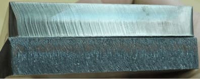
The quality of cut in stainless steel plasma cutting depends on the type of gas (plasma gas- Argon- Hydrogen mix, or compressed air) as shown in the below picture. The black color is due to nitrogen present in the air.
Will Plasma Cutter Cut Aluminum?
Straightforward answer- Yes. A plasma cutter can be used effectively and economically for cutting Aluminum & it’s alloys.
Plasma Arc Cutting is one of the most widely used cutting processes for aluminum materials along with Laser cutting & water jet cutting.
Safety in Plasma Arc Cutting Process
Plasma Arc Cutting gives pronounced arc glare, spatter, fumes and noise. It is necessary to protect operators and other persons working in the vicinity from exposure to these unpleasant aspects. It is especially important that fume and noise are controlled.
One way to control fumes is to place the plate to be cut on a cutting table, which is filled with water up to the bottom surface of the plate.
The plasma jet releases gases at high speeds, which strike the water and produce turbulence in it. All the fume particles get trapped in the turbulent water.
The noise is controlled by using what is termed a water muffler in conjunction with the water table described above.
The muffler is in the form of a nozzle that is attached to the torch body and releases a curtain of water around the front of the torch.
The water required by the nozzle is pumped from the water table. The water curtain around the torch and the water surface of the table combine to form a sound-muffling shield around the arc.
The water muffler must not be confused with water shielding and water injection used in the modified systems of PAC.
Material Welding is run by highly experienced welding engineers, welding trainers & ASNT NDT Level III bloggers.
We strive to provide most accurate and practical knowledge in welding, metallurgy, NDT and Engineering domains.


 Steel")

