E71T-1C Welding Filler Wire
E71T-1C Welding Filler Wire is Flux cored arc welding consumable used for welding of carbon steel, mild steel and low alloy steel materials.
Both the EXXT-1C i.e., E60T-1C or E70T-1C (XX can be 60 or 70) and EXXT-1M i.e., E60T-1M or E70T-1M electrodes have similar type slags and are designed for single and multiple pass welding using Direct Current Electrode Positive (Reverse polarity).
Meaning of E70T-1C and E70T-1M
The meaning of ‘C’ and ‘M’ in E70T-1C or E70T-1M are:
- ”C” means wire to be used with 100% CO2 shielding gas.
- “M” means that the wire to be used with 75%–80% Argon/balance CO2 shielding gas.
EXXT-1C (XX can be 60 or 70) and EXXT-1M gives good appearing weld bead finish with low welding spatters and a spray transfer mode. E71T-1C rod has a rutile coating and can give a high welding output.
E71T-1C Chemical Composition and mechanical properties
E71T-1C Chemical Composition and mechanical properties are given in below table. E71T-1C chemical compositions are Carbon, Manganese, silicon mainly with additional alloying of chromium, nickel and molybdenum in small amounts.
| Element | Range |
|---|---|
| Carbon |
0.12% Max. |
| Manganese | 1.75% Max. |
| Silicon | 0.90% Max. |
| Phosphorus | 0.03% Max. |
| Sulfur | 0.03% Max. |
| Nickel | 0.50% Max. |
| Chromium | 0.20% Max. |
| Molybdenum | 0.30% Max. |
| Vanadium | 0.08% Max. |
| Copper | 0.35% Max. |
| Properties | Value |
|---|---|
| Tensile Strength, Ksi (MPa) | 70-95, (490-670) |
| Yield Strength, Ksi (MPa) |
58 (400) |
| Elongation, % minimum | 22 |
| Toughness | 20 ft·lbf at –0°F (27J at-20°C) |
E71T-1C Welding Wire Specifications
E71T-1C or E71T-1M flux-cored wire is supplied as per the SFA No. 5.20 (AWS A 5.20) (SFA 5.20 can be found in ASME Section IIC).
The ISO specification or standard for E71T-1C is BS EN ISO 17632.
AWS A5.20 is FCAW filler wire specification covering all carbon steel welding cored filler wires.
E71T-1C Meaning
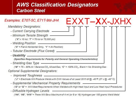
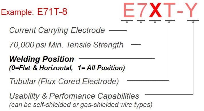
The meaning of E71T-1C welding wire is:
- ‘E’: Refer Electrode
- Next digit (6 or 7 for example) means electrode minimum tensile strength in Ksi multiplied by 10.
- Third digit refer to the welding position, 0 mean Flat & horizontal and 1 mean all positions.
- Fourth digit, ‘T’ means Tubular wire.
- Next digit after hyphen is the electrode usability characteristics. For example, in E71T-1C wire, 1 mean that wire can be used with DCEP. There can be 1 to 14 number or also can be written as ‘G’.
- Next digit either ‘C’ or ‘M’. The letter “C” means that this rod is classified using 100% CO2 shielding gas. The letter “M” means that the wire is classified using 75%–80% Argon/balance CO2 shielding gas.
- ‘H’ given at the end of the electrode classification refer to the amount of diffusible hydrogen present in the weld deposit.
- It will be H4 or H8 or H16. For example, ‘H4’ mean 4 ml of Average Diffusible Hydrogen can present in maximum of mL/100g Deposited Metal.
A detailed overview is given in the below figure.
A simple classification is given in the below figure.
Toughness requirements for E71T-1C
Weld deposit Toughness requirements are not mandatory for the flux-cored wires and are usually agreed upon between the purchasers.
These are optional and can be decided by the purchaser of the wire. If stated, the letter “J” when present in the electrode classification (E.g., E71T-1CJ) states that the welding wire meets the requirements for improved weld metal toughness and will deposit a weld metal with Charpy V-Notch properties of at least 20 ft·lbf at –40°F (27J at –40°C).
Welding Polarity for E71T-1C
The E71T-1C can be used only with DCEP polarity. Here, ‘1’ at the third digit, means the electrode is meant for Direct Current Electrode Position polarity only.
Types of polarity in SMAW, MIG, MAG, FCAW, TIG, and SAW
Difference between E71T-1C and E71T-1M
The main difference between E71T-1C and E71T-1M is the type of shielding gas used. Where C means the shielding gas as pure CO2, ‘M’ refers to the gas mixture of Argon and CO2 (usually 75%–80% Argon/balance CO2 shielding gas).
Shielding gases for MIG-MAG, TIG, and FCAW welding and shielding gases purity
Storage of Difference between E71T-1C and E71T-1M
The storage of E71T-1C and E71T-1M is very crucial. These are cored wire which means they have flux coating. These flux coating can absorb the moisture from the atmosphere easily and will result in welding porosity.
Thus, storing them in a controlled atmosphere such as a humidity-controlled storeroom is mandatory. The storing temperature can be kept to ambient temperature of 70 -85°F (20 to 30°C and humidity of 30 to 55%.
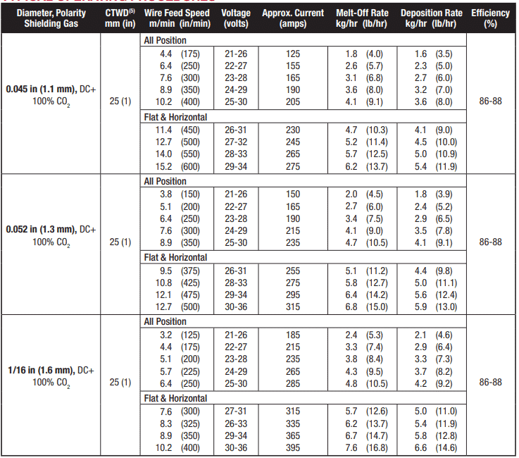
Selection of current for E71T-1C and E71T-1M
The welding current shall be kept to a controlled limit if welding for toughness application. As high heat input will be going to reduce the weld toughness.
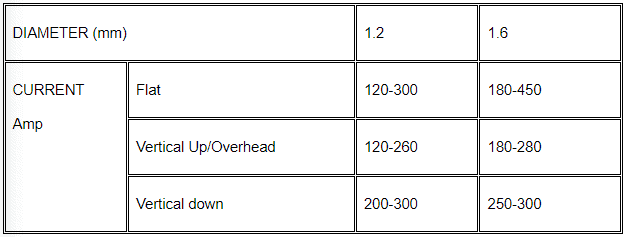
The typical welding current for 1.2 mm E71T1-C wire in a flat position is 120 to 300 amperes depending upon the material thickness and type of weld.
For example, welding a fillet weld in 25 mm thickness, one can go up to 300 amperes but when welding an open root in groove weld, he will need only 100 to 130 amperes current only.
Higher content of argon present in the argon-CO2 mixture will reduce the manganese & silicon losses due to fewer elements reacting with oxygen resulting from CO2 shielding dissociation, along with losses of some other elements such as chromium.
This reduction of loss for elements especially for manganese will result in the increase of yield strength and tensile strength of the weld deposit and silicon will provide a good bead finish. This can also influence the weld deposit toughness properties.
FCAW Wire diameters and position limits
Welding filler wire of bigger dia. (E.g., 5/64 inches or 2 millimeters and larger) wire of E71T-1C or E71T-1M is mainly used for 1G, 2G, 1F & 2F welding positions.
The smaller dia. filler wire from 1/16 inches or 1.6 millimeters & 0.052 inches (1.2 mm) can be used for all position welding.
Read more: Flux Cored Arc Welding (FCAW)
Read more:
- BS EN ISO 17632
- Microsoft Word – 71T-1C,-1M (washingtonalloy.com)
- K-71T | Line-Up | Products – KISWEL
Similar Posts:
- ER70S-6 welding wire MTC, specification, chemical-mechanical properties
- E7018-1 or E4918-1-H4 electrode specification, meaning, chemical & mechanical properties with MTC
- What are the differences Between NR-211-Mp and E71T-1?
")


