Determining the minimum necessary pipe wall thickness for a given pipe diameter and selecting the actual pipe thickness for design purposes is one of the basic tasks for any piping project. Designers need to determine the required piping wall thickness according to standards like ASME B31.3 to withstand internal line pressure. An important formula for calculating pipe thickness (where t is less than D/6) is commonly used:
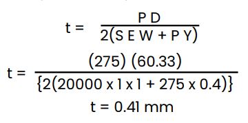
t = (PD)/ 2(SEW + PY)
tm = t + c
Where,
t = Pressure design thickness, as calculated in accordance with internal pressure or external pressure.
c = Sum of mechanical allowances ( thread or grove depth) plus corrosion and erosion allowance.
D = Outside diameter of the pipe as listed in tables of standards or specifications or as mentioned.
E = Quality factor from Table A-1B.
P = Internal Design Pressure gauge.
S = Allowable stress value for material from Table A-1
tm = Minimum required thickness, including mechanical, corrosion and erosion allowances.
W = Weld strength reduction factor in accodance with Table 302.3.5.
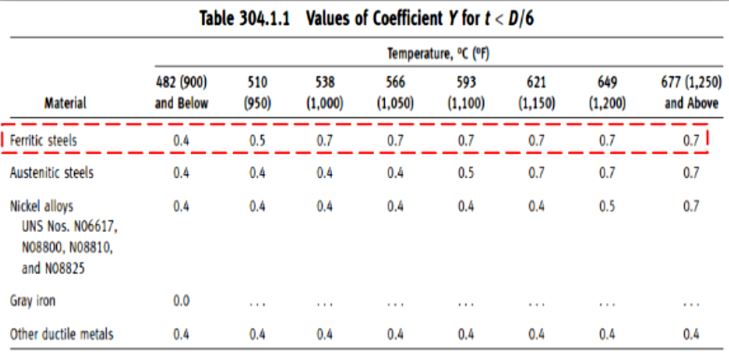
Y = Coefficient from Table 304.1.1.
Pipe thickness Calculation Example
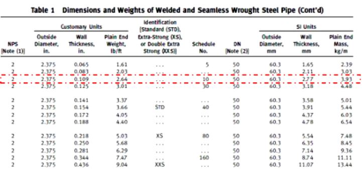
Assume we have a ASTM A106 Gr B CS seamless pipe of 2-inch NPS. The design temperature is 100 ºF with a design pressure of 275 Psig. Consider a Mechanical, Corrosion and erosion allowance of 1.5 mm and mill tolerances of 12.5% of the thickness.
From this given information, we can get the following input:
P = 145 Psig,
NPS = 2″
Pipe OD = 60.33 mm
Design temperature (T) = 100 ºF.
Calculator
Pipe Design Thickness Calculator
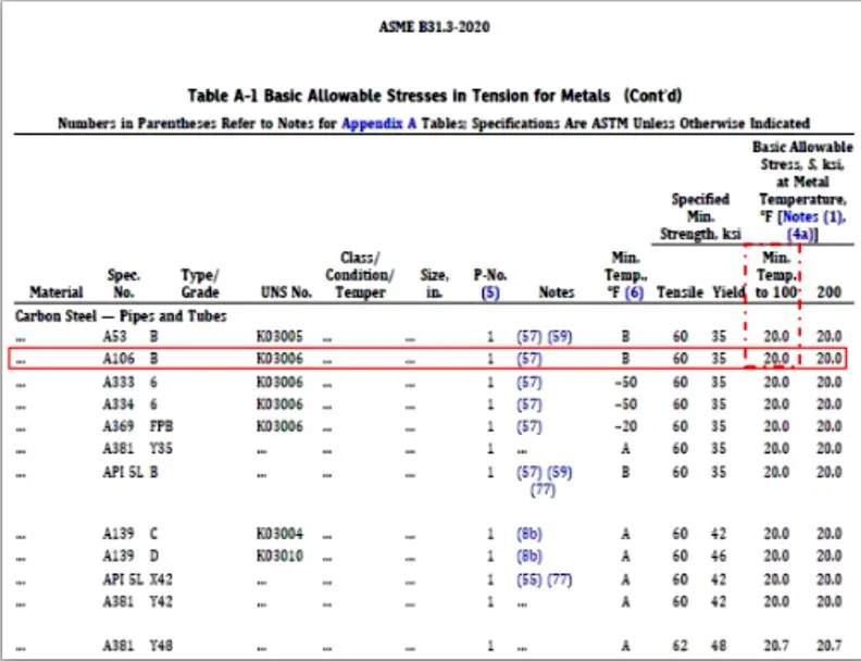
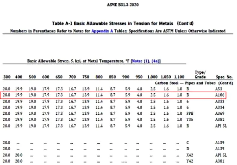
For the design situation, we can consult Table A-1 of ASME B31.3 to determine the Allowable Stress (S) for the pipe material, in this case carbon steel (ASTM A 106 Gr.B).
Based on the given parameters for this problem: T = 100°F, Material = ASTM A106 Gr. B We can determine from the table that the allowable stress, S, is 20 ksi or 20,000 psi.
When determining the required wall thickness of pipes to withstand internal pressure, a weld efficiency factor, E, is used in the calculation to account for any reductions in strength due to welds or joints. This weld efficiency factor typically ranges from 0.6 to 1.0, with 1.0 representing full efficiency without any strength reductions.
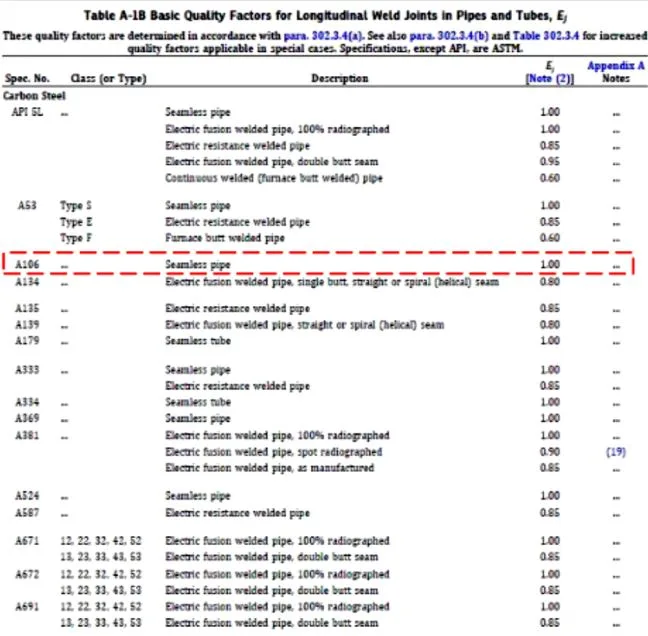
For seamless pipes without any welds, a weld efficiency factor of 1.0 is used according to the ASME B31.3 code. Since our pipe in this case is seamless, the weld efficiency factor, E, is 1.
The ASME B31.3 code provides Table A-1B which specifies the appropriate weld efficiency factor for various pipe fabrication methods. For seamless pipes, the table specifies a value of 1.0 for the weld efficiency factor, E.
The weld joint strength reduction factor, denoted by W, represents the ratio of the stress required to cause failure in a weld joint compared to the stress required to cause failure in the base material, at the same elevated temperature and duration of exposure. This factor only applies to longitudinal and spiral welded pipes, as weld joints in these pipes may have lower creep rupture strength at high temperatures compared to the base metal.
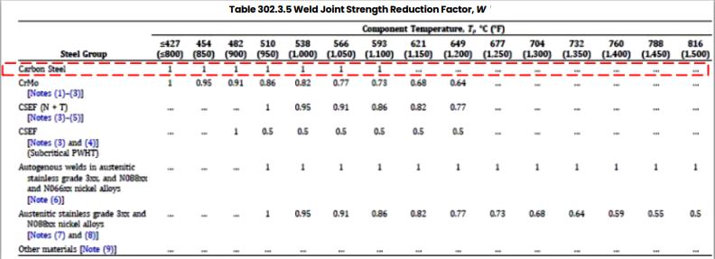
Weld joint strength reduction factors are used to account for this potential reduction in strength at weld locations. The value of W can be found in ASME B31.3 Table 302.3.5 and varies based on the material, temperature, and exposure duration.
However, for the case of a seamless pipe without any welds as described in the problem statement, the weld joint strength reduction factor W is equal to 1, since there are no weld joints present. The value of W for a seamless pipe is 1, according to the ASME B31.3 code.
The factor Y, which depends on the temperature of the piping system, affects the calculation of required pipe wall thickness. At higher temperatures, Y increases, resulting in a lower calculated wall thickness needed to withstand the same internal pressure.
The ASME B31.3 code provides Table 304.1.1 which specifies appropriate values of Y for different materials and temperatures. The table is valid when the calculated wall thickness, t, is less than D/6 and for the materials listed.
Values of Y for intermediate temperatures can be interpolated from the table values. For carbon steel ASTM A106 Grade B, which is the material in this problem, the table specifies a Y value of 0.4.
Calculation
Step: 1
Based on all above input and using the formula, t = (PD)/ 2(SEW + PY), we will have:
Step: 2- add corrosion allowances to the t- calculated above.
tm = t + c
t m = 0.41 + 1.5
tm = 1.91 mm
Step: 3- Now add the pipe mill tolerances to the tm calculated above.
The calculated wall thickness, tm, refers to the minimum required thickness after accounting for manufacturing tolerances. During the pipe manufacturing process, the actual wall thickness can be up to 12.5% less than the specified design thickness.
Therefore, designers must provide an additional 12.5% cushion to ensure the final as-built wall thickness meets the minimum required value, tm, even after accounting for manufacturing tolerances.
To calculate the nominal wall thickness that should be specified in the design, we apply a factor of 0.875 to the minimum required thickness, tm, as follows:
tm / 0.875 = Nominal thickness
For the given example where tm = 1.91 mm:
1.91 mm / 0.875 = 2.18 mm
Therefore, the nominal wall thickness that should be specified in the design is 2.18 mm. This accounts for a possible 12.5% decrease in thickness during manufacturing, still resulting in a minimum as-built thickness of at least 1.91 mm.
Step 4: Choose a near matching ordering thickness in ASME B36.10M.
Material Welding is run by highly experienced welding engineers, welding trainers & ASNT NDT Level III bloggers.
We strive to provide most accurate and practical knowledge in welding, metallurgy, NDT and Engineering domains.


")

