Delong Diagram clarifies the Schaeffler diagram (Both are constitute diagrams) using the Nitrogen in the calculation as we know Nitrogen is a very powerful austenite stabilizer. While Schaeffler Diagram does not use Nitrogen in its calculations. Another modification in the Delong diagram is the use of Ferrite Number (FN) to represent the ferrite content.
The chromium (Cr Eq.) equivalent is calculated using same equation as in Schaeffler Diagram although the Ni Equivalent (Ni Eq.) is adjusted to below equation: Ni (eq) = Ni + (30 x C) + (0.5 x Mn) + (30 x N).
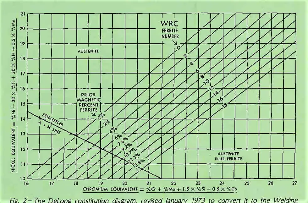
The Delong diagram, with Cr-Eq and Ni-Eq, is given below. The diagram gives Ferrite level as a percentage along with the ferrite number ‘FN‘.
As can be seen, the Delong Diagram includes only a limited portion of the alloys recorded in the Schaeffler diagram.
It is valid for Nickel equivalents between 10% to 31% and chromium equivalents between 16% to 27%.
It can be used to effectively predict the microstructure of metastable austenitic chromium-nickel steels that form at room temperature.
Delong Diagram Calculator
To use DeLong diagram calculation, we need to first calculate the Cr Equivalent. Cr-Equivalent is plotted on the X-axis & is calculated using the below formula:
What is the main purpose of prediction diagrams like Schaeffler diagram or Delong diagram?
A major drawback of the Schaeffler diagram is that it ignores the significant influence that nitrogen has on the phase balance of austenitic stainless steels, since this element is a strong austenitiser.
Many heats of austenitic stainless steels have been found to contain appreciable amounts of nitrogen. Also, samples of weld-metal have often registered either high or low nitrogen, because of excessive arc length or improper welding technique.
The revised constitution diagram is known as Delong diagram and is shown in above figure.
While Schaeffler used the metallographic method for determining the ferrite percentage in weld-metal, Delong has used a magnetic measuring instrument in his work. Accepting that this is a secondary measurement system,
Delong has adopted an arbitrary standard called ferrite number (FN), to indicate the ferrite content. The ferrite number and the ferrite percentage are identical at low levels of ferrite, but they differ widely when the ferrite levels are high.
Practical uses of Delong Diagram
To understand the resistance of the duplex weld-metal structure to micro-fissuring, one must trace the weld solidification process.
Depending on the relative proportions of ferrite-forming and austenite-forming elements present, the weld-metal solidifies initially as grains of delta-ferrite or as grains of austenite.
As solidification proceeds, initial ferrite grains undergo solid-state transformation to austenite grains, mainly in the grain centers. If sufficient ferrite forming elements are present, residual pools of delta-ferrite remain in the microstructure.
The remaining weld-metal and the grains that have solidified initially as austenite, remain fully austenitic down to room temperature. When the final transformation provides a duplex structure, it greatly increases the number of phase boundaries.
As a result, the low-melting point constituents which promote micro-fissuring get distributed over a larger area and thereby the likelihood of fissures in the weld-metal is minimized.
Minimum Ferrite Requirements to Avoid Micro-Fissuring
Different weld-metals require different levels of ferrite to eliminate micro-fissuring. For E 16-8-2, E 308, E 308L, E 316 and E 316L, at least 3 FN is required. For E 309, it is 4 FN; for E 318 it is 5 FN and for E 347 it is 6 FN.
A high ferrite level is required in E 347 weld-metal to counteract the cracking tendency promoted by a low-melting eutectic phase formed by columbium.
It is difficult to control fissuring in E 310 Cb weld-metal because of the presence of columbium, and the fact that it is not possible to obtain ferrite in the weld-metal of this composition.
The best one can do is to restrict the contents of Si, S and P. Like E 310 Cb, E 310, E 310 (Mo) and E330 weld-metals also invariably deposit a fully austenitic weld-metal.
The presence of ferrite lowers the corrosion resistance of austenitic steel weld-metal to a marginal extent, which can be ignored in most applications. There are, however, important exceptions.
For example, 18 Cr-12 Ni-Mo weld-metals such as types E 316, E 317, and E 318 suffer localized corrosion attack on the ferrite in certain media in the as-deposited condition. The corrosion can be prevented by either annealing the joint or using ferrite-free weld-metal.
In the fabrication of urea plant, E 316 type weld-metal with ferrite content of 2% maximum is specified for the components which come into contact with the extremely corrosive carbamate solution.
Effect of High Temperature Service on Duplex Stainless Steel Weld
When weldments having duplex weld-metal microstructure are exposed to service temperatures in the range of 480-900°C, various intermetallic phases are formed in varying amounts depending on the chemical composition, the ferrite content and the time at temperature.
With increasing ferrite content, the transformation is accelerated and the temperature at which it occurs is lowered. The transformation occurring in non-molybdenum bearing stainless steels is termed sigma-phase, and those occurring in Mo-bearing steels are referred to as sigma- and chi-phase transformations.
Nucleation of these phases occurs at the austenite-ferrite boundaries and growth is primarily towards the center of the ferrite. The presence of these intermetallic is viewed seriously, because they lower ductility and impact resistance of the weldment.
Ductility lost by sigma-phase formation can be restored to a large extent by heating the steel at 1,038° C for a short time. For converting sigma completely to austenite, heating to a temperature as high as 1,230° C is required.
Heating to such a high temperature poses the danger of grain growth and consequent changes in mechanical properties.
Material Welding is run by highly experienced welding engineers, welding trainers & ASNT NDT Level III bloggers.
We strive to provide most accurate and practical knowledge in welding, metallurgy, NDT and Engineering domains.