Bend Test in Welding plays important role to determine the soundness and ductility of welds.
Bend testing is the most commonly, economical and simple qualitative mechanical testing used to check the material ductility and soundness.
The test is more commonly applied as a QC tool to butt/ groove weld joints (For procedure or performance qualification) compare to materials.
The test is simple in operation and requires the least equipment setup and operator skills.
The test is usually carried out using a Universal testing machine, but a simple setup can be made on the shop floor very easily.
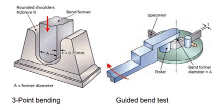
Bend Test Procedure (Guided Bend Test)
Bend tests are usually carried out on a universal testing machine (UTM) using a 3 or 4-point bend fixture.
The bend test uses a test specimen that is bent in three-point bending to a specified angle.
In the Guided bend test the test specimen is wrapped around a former of a given diameter as per the test specification.
The guided bend test is the most common test method used for welding procedure qualification (PQR) and welder performance qualification specifications. The former diameter depends on the test specimen thickness.
Two main types of bend tests i.e. 3 point bending and guided bend test are shown in the below figure.
The outer portion of the bend test takes the maximum expansion by plastic deformation under tensile stresses.
This results in the revelation of any flaws easily with a premature bend test failure. Standards generally indicate a defect of 3mm or more to be rejected.
For material thickness less than 12 mm (1/2 inch), transverse root and face bend tests are carried out. For the base metal thickness of more than 12 mm (1/2 inch), generally, side bend tests are used by using full cross-sectional thickness.
The bend test is being used in welder performance tests to substitute the NDT. We normally use RT or UT for welder qualification to test the weld soundness but we can also opt for Bend testing to substitute these NDT tests as permitted in ASME Section IX.
We can do root bend & face bend tests according to the details given in ASME Section IX, Table QW-452.1(a). We can choose either the NDT method or mechanical testing as permitted by the code.
There is a restriction on although on some welding processes and welders can only be qualified by bend test and radiography and ultrasonic will not be acceptable.
The bend test is a qualitative destructive test as we will not get any test result values except whether the result is acceptable or not. The main objectives of the bend tests are:
Check the weld soundness for welder/ operator performance qualification.
Check the weld joint ductility for welding procedure qualification (PQR).
Verify the material ductility when the test is performed for base metal only.
Type of Test Specimen for Bend Test in Welding
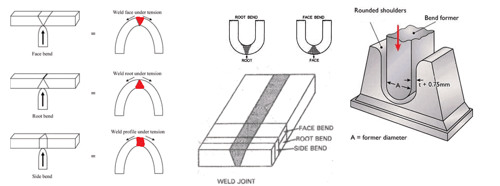
Bend Test in welding has different types to test the material in different conditions such as testing in longitudinal, transverse (for base metal or weld coupons), and face or root side bend in case of welding test coupons.
The main type of bend tests are given below and also shown in the sketch:
Face bend: When the load is applied on the root side so that the weld face will be in the tension.
Root Bend: Here load is applied on the face side so that the weld root will be in the tension.
Side bend: The load is applied on any of the sides of the specimen cut transverse to the welding direction.
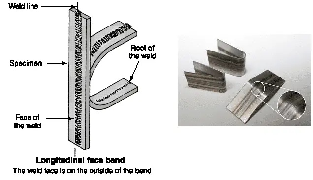
Longitudinal Bend: The longitudinal bend also has two types: a) face longitudinal and b) root longitudinal depending on the direction of the load applied similar to face and root bend as shown in the below diagrams.
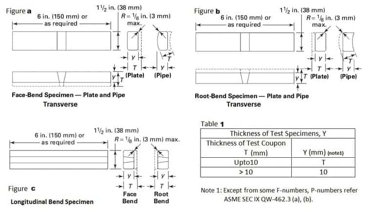
Face, Root, Transverse & Longitudinal Bend Specimens dimensions
The dimensions of the bend test coupon taken from plate butt weld and pipe butt weld are given below.
In Figures, a, b, and c below, the dimensions of the Face bend Root transverse bend, and Longitudinal bend specimen are shown.
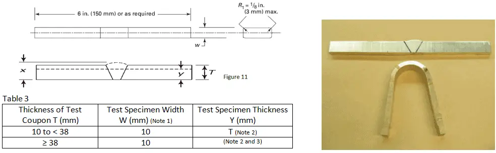
The thickness, width, and length of the bend specimen are based on the test coupon thickness as shown in the below figure. The generally used width of the bend test is 38 mm and the length of the specimen is a minimum of 150 mm as per ASME Section 9.
Side Bend Specimens dimensions
The Bend Test Specimen dimensions as per ASME Section IX are given below for side bend and transverse bend specimens.
As permitted in ASME Section IX, Table QW-451.1, Footnote 5, a material having thickness less than 10 mm (3/8 inches) root bend & face bend in weld are required.
For thickness more than 3/8-inches or 10 mm, these can be substituted by a side bend test.
When weld deposit t is less than coupon thickness T, side-bend specimen thickness may be ‘t’.
When coupon thickness T equals or exceeds 1-1/ 2 in. (38 mm), use one of the following: (a) Cut specimen into multiple test specimens of thickness y of approximately equal dimensions 3/ 4 in. to 1-1/ 2 in. (19 mm to 38 mm). y = tested specimen thickness when multiple specimens are taken from one coupon. (b)The specimen may be bent at full width. See requirements on jig width in QW-466.1.
Bend Testing Standards
The bend testing standards are for material testing and weld joint testing. The main standard for bend testing for material testing (such as plate, pipe, forging, etc.) is ASTM E290.
The bend testing standards for welding are ASTM E190 & ASME Section IX. Below are the main bend test standards:
As per ASME Section IX following rules are applied for bend test result acceptance:
1. No discontinuity shall be more than 1/8 inch (3 mm) in the length (in any direction) must be noticed in the convex surface (Outer side of the bend specimen after bending) after the test.
2. Any resultant crack & other discontinuity which are less than 1/8 inch (3mm) shall be acceptable. In case of cracks that are more than 1/8 inch (3 mm) but initiated from the edge of the test coupon, is acceptable.
The reason is that the edges are subjected to stress concentration due to the test & should not be a reason for rejection.
As the bend test is a mandatory test requirement as per ASME Section IX for PQR qualification, the result of bend tests must be recorded in the procedure qualification record (PQR).
The same rule applies if the bend test is used for welder qualification in lieu of NDT.
Bend Test Machine Price
Bend test can be performed either on a special bend testing machine or using the jigs on Universal Testing Machine as shown in the picture shown above. So, the cost can be USD 3000 to USD 30000 for the machine.
Bend Test mandrel diameter
The selection of the bend test mandrel diameter is as per the applicable code or standard. For example, when performing bend testing for welder qualification as per ASME Section IX, the bend test mandrel diameter is selected as specified in Figures QW-466.1 & QW-466.2.
For the base material bend test, the mandrel diameter requirements are specified in the ASTM E290 specification.
For bend testing for welder qualification as per ISO 9606-1 or ISO 15614-1, the mandrel diameter selection can be done according to ISO 5173.
What defects can a bend test show?
The bend test is a destructive test that is able to reveal a number of welding defects but is limited to the surface, sub-surface defects. Internal defects can reveal subjected to that the material lacks ductility so it can break.
A Free bend test or also called the initial bend test. The test is easy to perform and requires no special equipment.
First, the bend specimens are cut from the welding test plate and prepared with a smooth surface. Any extra face or root reinforcement is ground smoothly.
An initial bend is created by clamping the bend test coupon in the vice and using a hammer manually.
The bend test than can be clamped entirely in the vice. Either a force using a hammer or from the vice can be used to make the final bend.
Due to the fact that in free bend, as the bending parameters can not be controlled, this type of bend does not reflect good quality results, and hence free bend test is not used too much. Also, this type of bend test is not endorsed by the test standards or specifications.
This test measures the ductility of the weld metal in a butt joint in a plate or pipe in terms of elongation percentage.
The thickness of the specimen is the same as that of the plate or the pipe, the width is 1.5 times the thickness and the length is anywhere between 150 mm for 6 mm ‘t’ and 450 mm for 50 mm ‘t’. The length is not mandatory.
The weld is dressed to the plate level by filing, grinding, or machining, bearing in mind that the tool marks should be lengthwise to the specimen.
It is important that the line between the weld metal and the base metal is distinctly visible, and if necessary the surface of the specimen should be etched with a suitable reagent.
Two gauge lines are lightly marked on the specimen. The distance between the gauge lines (gauge length) should be 3 mm less than the width of the weld.
It should be measured to the nearest 0.25 mm. Gauge lines must appear on the wider face of the weld if it has unequal faces.
The specimen is first subjected to an initial bend in a device. The face having gauge lines must face downwards.
The weld should lie exactly at the midspan of both the supports and the loading block. Alternatively, a bend of 30-45° away from the gauge lines may be given by holding the specimen in the jaws of a vice with one-third length of the specimen projecting from the jaws and giving hammer blows.
A similar bend is given to the other end of the specimen. Both ends should be bent through the same angle, and be symmetrical with respect to the weld.
The final free bend is achieved by applying compressive forces to the two ends to gradually decrease the distance between them.
If a crack or depression exceeding a specified size appears on the convex face of the specimen, the load is withdrawn and the specimen removed. If no cracks or other defects appear, the specimen is bent completely to 180° and then taken out.
In either case, the final gauge length is measured to the nearest 0.25 mm. The difference between the final and original gauge length divided by the original gauge length and multiplied by 100 gives the elongation percentage which is taken as a measure of weld metal ductility.
Material Welding is run by highly experienced welding engineers, welding trainers & ASNT NDT Level III bloggers.
We strive to provide most accurate and practical knowledge in welding, metallurgy, NDT and Engineering domains.