In Ultrasonic Testing, the use of display makes the user understand, locate and identify the flaws. There are a number of display types being used by the machine manufacturer based on the user’s need.
This article details the main types of UT displays. Scanning is the general term used for the process of moving the transducer (UT Probe) over or along the test object.
What are the Types of Ultrasonic (UT) Scanning Displays?
The main types of UT or Ultrasonic scanning displays are:
A-Scan
B-Scan
C-Scan
D-Scan
S-Scan
What is A-Scan Display in Ultrasonic Testing?
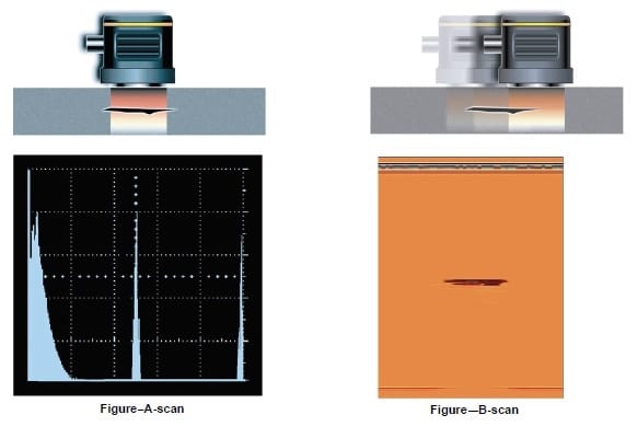
The A-Scan is a one-dimensional presentation of time versus the amplitude on the UT machine screen.
It shows the existence of flaws (if any present during scanning), and their position, and also gives an estimate of their sizes.
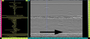
Time vs. amplitude, as shown in the Figure below (left side), is the most efficient way of revealing the discontinuities.
A-Scan displays the response along the path of the sound beam for a given position of the probe. It also displays the amplitude of the signal originating from the discontinuity as a function of time on the screen.
The discontinuity depth (back wall echo) and time of flight are shown on x-axis. The ‘y’ axis indicates the amplitude of reflected signals (echoes) and can be used to estimate the size of a discontinuity compared to a known reference reflector.
What is B- Scan Display in Ultrasonic Testing?
The B-scan display as shown in the above figure right-hand side shows reflection (cross-sectional view) from the top and bottom of the test object & flaws as the probe moves along a line (one axis).
The advantage of this type of presentation (B-Scan) is that both the length of the flaw and its depth below the surface is revealed.
The horizontal axis on the scan connects to the probe position as it moves along the test object surface and gives information on the flaw.
On the ultrasonic machine display, a colored or gray scale intensity is used to display echo amplitude. The main applications of B-Scan are in the medical field.
What is C-Scan Display in Ultrasonic Testing?
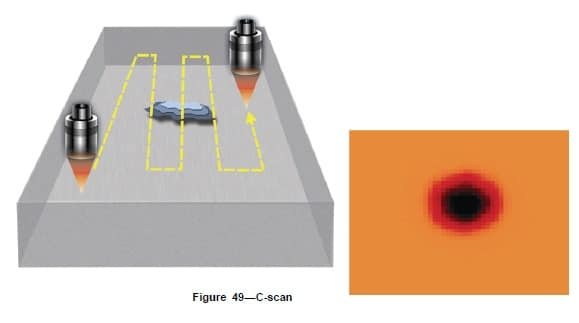
The C-Scan is analogous to a radiograph film. The external details of the test object are projected onto a plane that is the UT machine screen.
In the C-Scan front and back surface reflections are not used, instead, the reflection from the flaw is the only one that is projected as shown in the below figure. This picture represents a C-Scan as a test object plane view.
A mechanical or electronic scan is used to display images by imaging in x-y direction or plane.
A coordinate system is made using the X-Y axis that shows the transducer/flaw position. Echo amplitude or discontinuity depth can be displayed by color/grayscale intensity.
What is D-Scan Display in Ultrasonic Testing?
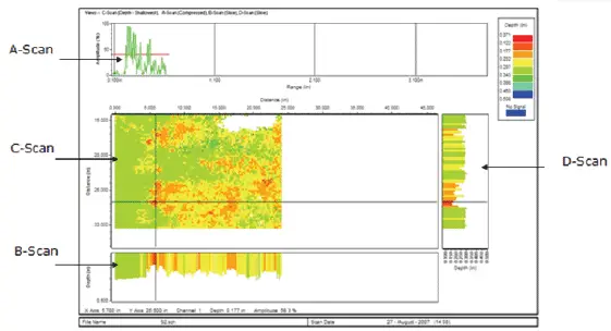
The D-scan as shown below Figure represents the test object cross-sectional view for full-thickness. The test specimen is perpendicular to the scanning surface.
D-Scan is the same as B-Scan. The difference is that the scan representation is perpendicular to the B-scan representation in the plane of the test object.
The D-scan allows quick differentiation of flaws along a weld by showing their location in depth from the scanning surface.
The below picture shows the D-Scan and its relationship with A, B & C-Scan in comparative views.
What is Phased Array S-Scan Display in Ultrasonic Testing?
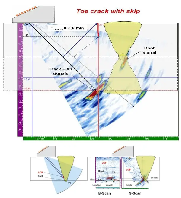
S-Scan in Phased array means Sector-Scan. A representation of S-Scan is shown in the below figure. The Scan shows a 2-D scanning of UT reflectors by plotting data from various angles at the same time.
The scan shows the picture of the cross-sectional area from the test object that has been scanned by the ultrasound. Here the size and location of the flaws can be measured in the scanned area.
As we know that a PAUT transducers has a numbers of elements usually 8 to 128 nos., and those elements are excited at intervals to generate the ultrasonic waves or let us say constructive interference.
This constructive interference is controlled by the amount of time delay in element excitation and can steer the sound through a range of angles. This array of beam angles is then plotted to create the sector scan.
The ultrasonic energy provides responses in a pulse-echo fashion as with conventional straight beam and angle beam techniques.
The sectorial or S-scan, is unique to phased array ultrasonic testing. Familiar to many from medical prenatal imaging, the S-scan is a pie-shaped representation of each A-scan acquired as the sound field is steered through a range of angles.
The PAUT inspector defines the start and end angle, as well as the angle-stepping resolution (for example, 0.5° or 1° steps), while the aperture remains constant. A-scan echo amplitude is mapped to a false-color scale.
For example, the low amplitude may be blue, while the high amplitude is red. This allows the intensity and location of test indications to quickly be judged by the inspector.
One may selectively view each A-scan on PAUT units. For visual convenience, the depth axis of A-scans is compressed to varying amounts so that echo locations directly correlate to their S-scan locations.
Time of Flight Diffraction (TOFD) B-scan and D-scan displays
Time of flight, or echo amplitude, for signals exceeding the A-scan data gate may selectively be displayed with respect to a position. C-scans allow for top-view reflector area and depth estimation using the time of flight information.
C-scan data may be obtained manually with the aid of an X-Y probe position encoder, but automated scanning is generally a faster and more robust approach.
A D-scan data representation is produced when the area scan data is plotted as an end view of the component, incorporating all data, as opposed to a slice.
The D-scan is perpendicular to B- and C-scan views and is three-dimensional unlike the B-scan, which is a 2D linear slice representation.
Types of UT Scanning
Ultrasonic Testing scanning can be divided into two types:
Contact Scanning
Immersion Scanning
What is Contact Scanning in UT?
In Contact Scanning– the transducer directly contacts the test object through a thin film of oil or some other suitable couplant such as water.
The contact immersion is widely used and suitable for manual scanning. It offers portability and is useful for field application and preventive maintenance inspection.
What is Immersion Scanning in UT?
Immersion Scanning– In this technique, the test object and transducer are both immersed in the couplant but are separated from each other.
One of the main requirements for this technique is that the back surface of the test object be supported so that the total contact with the container bottom is avoided.
Jiten Karmakar is an NDT Specialist, holding ASNT NDT Level III and ISO 9712 NDT Level III Qualifications. He is having vast hands-on practical and theoretical experience with all major NDT Methods and technique.
 important formulas & Calculations")


 Quiz?")

 thickness gauging?")
")